
User Manual

Rockwell Automation Publication 1756-UM540A-EN-P - May 2014 175
Isolated Analog I/O Module Tag Definitions Appendix A
1756-IF8I Module Tags
This section describes the tags associated with the 1756-IF8I module.
Configuration Tags
The following table describes the Configuration tags associated with the
1756-IF8I module.
IMPORTANT
Each application’s series of tags varies but no input module application
contains any tags that are not listed here.
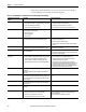
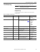
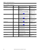
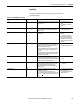
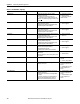
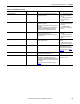
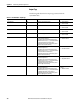
Table 20 - 1756-IF8I Module - Configuration Tags
Tag Name Size Definition Valid Values
Ch[x].InputRange SINT Channel’s operating range. • 0 = -10…10V
• 1 = 0…5V
• 2 = 0…10V
• 3 = 0…20 mA (default)
Ch[x].NotchFilter SINT Notch Filter removes line noise for the channel.
There is a relationship between this setting and the RPI
setting. For more information on Notch Filter, see page 48
.
• 0 = 10 Hz
• 1 = 50 Hz
• 2 = 60 Hz (default)
• 3 = 100 Hz
• 5 = 1000 Hz
• 6 = 20 Hz
• 7 = 15 Hz
• 8 = 500 Hz
• 9 = 5000 Hz
• 10 = 5 Hz
Ch[x].AlarmDisable BOOL Disables all alarms on the module. • 0 = Enabled
• 1 = Disabled (default)
Ch[x].ProcessAlarmLatch BOOL Latches all Process alarms if they are configured not to
clear until explicitly unlatched.
• 0 = Latching disabled (default)
• 1 = Latching enabled
Ch[x].RateAlarmLatch BOOL Latches all Rate Alarms when set so that they do not clear
until explicitly unlatched.
• 0 = Latching disabled (default)
• 1 = Latching enabled
Ch[x]. Disable BOOL Disables the channel. • 0 = Enabled (default)
• 1 = Disabled
Ch[x].Sourcing BOOL When in current mode, indicates if channel is Sinking or
Sourcing.
• 0 = Sinking (default)
• 1 = Sourcing
Ch[x].SynchronizeSampling BOOL Determines if the sampling of the channel is synchronized
with other channels configured as synchronized.
• 0 = Not synchronized (default)
• 1 = Synchronized
Ch[x].DigitalFilter INT Time Constant for a First Order Lag filter. 0…32,767 ms
(0 = default)