
User Manual

Rockwell Automation Publication 1756-UM540A-EN-P - May 2014 113
Install ControlLogix Isolated Analog I/O Modules Chapter 6
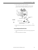
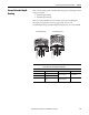
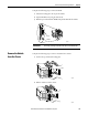
Spring Clamp RTB - Catalog Number 1756-TBS6H
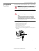
1. Strip 11 mm (7/16 in.) maximum length of wire.
2. Insert the screwdriver into the outer hole of the RTB to depress the spring-
loaded clamp.
3. Insert the wire into the open terminal and remove the screwdriver.
4. Insert the wire into the open terminal and remove the screwdriver.
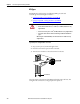
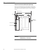
The open section at the bottom of the RTB is called the strain relief area. The
wiring from the connections can be grouped with a plastic tie.
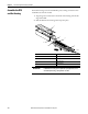
RTB Wiring Recommendations
Consider these guidelines when wiring your RTB.
• Begin wiring the RTB at the bottom terminals and move up.
• Use a tie to secure the wires in the strain relief (bottom) area of the RTB.
• For applications that require heavy gauge wiring, order and use an
extended-depth housing, catalog number 1756-TBE. For more
information, see page 115
.
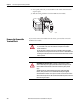
IMPORTANT
Make sure the wire, and not the screwdriver, is inserted into the open terminal
to prevent damage to the module.
Strain Relief Area