
User Manual

Rockwell Automation Publication 1756-UM540A-EN-P - May 2014 101
1756-OF8I Isolated Analog Output Module Chapter 5
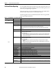
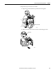
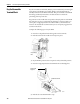
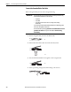
Figure 24 - 1756-OF8I Module Wiring Diagram - Voltage Output Type
1
3
5
7
019
1112
4131
6151
8171
0291
2212
4232
6252
8272
0392
2313
33
6353
2
34
8
6
4
+
–
OUT_0/V
OUT_0/I
RTN_0
Not used
OUT_2/V
OUT_2/I
RTN_2
Not used
>1000 User
Analog Output
Device
OUT_4/V
OUT_4/I
RTN_4
Not used
OUT_6/V
OUT_6/I
RTN_6
Not used
Not used
Not used
OUT_1/V
OUT_1/I
RTN_1
Not used
OUT_3/V
OUT_3/I
RTN_3
Not used
OUT_5/V
OUT_5/I
RTN_5
Not used
OUT_7/V
OUT_7/I
RTN_7
Not used
Not used
Not used
IMPORTANT: Remember the following:
• If separate power sources are used, do
not exceed the specific isolation
voltage. For more information on
module specifications, see the 1756
ControlLogix I/O Specifications
Technical Data, publication
1756-TD002
.
• Place additional devices anywhere in
the loop.