
User Manual

10 Rockwell Automation Publication 1756-UM540A-EN-P - May 2014
Chapter 1 Isolated Analog I/O Module Operation in the ControlLogix System
• Verify that you have an RTB or IFM and its components.
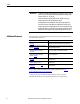
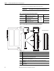
Figure 1 - Parts Illustration of the ControlLogix Isolated Analog I/O Module
IMPORTANT
RTBs and IFMs are not included with your module purchase.
Table 1 - Types of ControlLogix Isolated Analog I/O Modules
Cat. No. Description RTB Used Page
1756-IF8I 8-point general purpose isolated analog
current/voltage input module
36-pin
(1756-TBCH or
1756-TBS6H)
45
1756-IRT8I 8-point isolated combined temperature and mV
sensing input module
65
1756-OF8I 8-point general purpose isolated analog
current/voltage output module
93
1
2
3
4
6
5
Removable Terminal Block
Item Description
1 Backplane connector - Interface for the ControlLogix system that connects the module to the backplane.
2 Top and bottom guides - Guides provide assistance in seating the RTB or IFM cable onto the module.
3 Status indicators - Indicators display the status of communication, module health, and input/output
devices. Indicators help in troubleshooting anomalies.
4 Connectors pins - Input/output, power, and grounding connections are made to the module through
these pins with the use of an RTB or IFM.
5 Locking tab - The locking tab anchors the RTB or IFM cable on the module, maintaining wiring
connections.
6 Slots for keying - Mechanically keys the RTB to prevent inadvertently making the wrong wire connections
to your module.