User Manual ControlLogix Eight-channel Isolated Analog I/O Modules Catalog Numbers 1756-IF8I, 1756-IRT8I, 1756-OF8I
Important User Information Read this document and the documents listed in the additional resources section about installation, configuration, and operation of this equipment before you install, configure, operate, or maintain this product. Users are required to familiarize themselves with installation and wiring instructions in addition to requirements of all applicable codes, laws, and standards.
Table of Contents Preface Studio 5000 Environment . . . . . . . . . . . . . . . . . . . . . . . . . . . . . . . . . . . . . . . . . . 7 Additional Resources . . . . . . . . . . . . . . . . . . . . . . . . . . . . . . . . . . . . . . . . . . . . . . . 8 Chapter 1 Isolated Analog I/O Module Operation in the ControlLogix System Before You Begin . . . . . . . . . . . . . . . . . . . . . . . . . . . . . . . . . . . . . . . . . . . . . . . . . . 9 Ownership . . . . . . . . . . . . . . . . . . . . . . . . . . .
Table of Contents RTD and Thermocouple Error Calculations. . . . . . . . . . . . . . . . . . . . . . . . RTD Error . . . . . . . . . . . . . . . . . . . . . . . . . . . . . . . . . . . . . . . . . . . . . . . . . . . Thermocouple Error . . . . . . . . . . . . . . . . . . . . . . . . . . . . . . . . . . . . . . . . . . Module Error at 25 °C (77 °F) . . . . . . . . . . . . . . . . . . . . . . . . . . . . . . . . . Thermocouple Resolution . . . . . . . . . . . . . . . . . . . . . . . . . . . . . . . . . . . .
Table of Contents Chapter 5 1756-OF8I Isolated Analog Output Module 1756-OF8I Module Features . . . . . . . . . . . . . . . . . . . . . . . . . . . . . . . . . . . . . . 93 Multiple Output Ranges . . . . . . . . . . . . . . . . . . . . . . . . . . . . . . . . . . . . . . 94 Channel Offset. . . . . . . . . . . . . . . . . . . . . . . . . . . . . . . . . . . . . . . . . . . . . . . 94 Ramping/Rate Limiting. . . . . . . . . . . . . . . . . . . . . . . . . . . . . . . . . . . . . . .
Table of Contents Chapter 8 Calibrate the ControlLogix Isolated Analog I/O Modules Difference between Calibrating an Input Module and an Output Module . . . . . . . . . . . . . . . . . . . . . . . . . . . . . . . . . . . . . . . . . . . . . . Calibrate in Program Mode. . . . . . . . . . . . . . . . . . . . . . . . . . . . . . . . . . . Calibrate the Input Modules . . . . . . . . . . . . . . . . . . . . . . . . . . . . . . . . . . . . . Calibrate the 1756-IF8I Module . . . . . . . . . . . . . . . . . . . .
Preface This manual describes how to install, configure, and troubleshoot your ControlLogix® isolated analog I/O module. You must be able to program and operate a ControlLogix controller to efficiently use your isolated analog I/O modules. If you need additional information, refer to Additional Resources on page 8. ControlLogix isolated analog I/O modules convert analog signals to digital values for inputs and convert digital values to analog signals for outputs.
Preface IMPORTANT Additional Resources In addition to the Studio 5000 Logix Designer™ application, version 21 or later, you can use your ControlLogix isolated analog I/O modules in RSLogix 5000 software, versions 18…20, projects. You must install Add-on Profiles (AOP) to use the modules in any Logix Designer application or RSLogix 5000 software project. This publication describes configuration with Logix Designer application.
Chapter 1 Isolated Analog I/O Module Operation in the ControlLogix System Topic Page Before You Begin 9 Ownership 11 Configure a Module 11 Direct Connections 12 Input Module Operation 14 Output Module Operation 17 Listen-only Mode 18 ControlLogix controllers use isolated analog I/O modules to control devices in a ControlLogix control system.
Chapter 1 Isolated Analog I/O Module Operation in the ControlLogix System • Verify that you have an RTB or IFM and its components. IMPORTANT RTBs and IFMs are not included with your module purchase. Table 1 - Types of ControlLogix Isolated Analog I/O Modules Cat. No.
Isolated Analog I/O Module Operation in the ControlLogix System Ownership Chapter 1 Every I/O module in the ControlLogix system must be owned by a ControlLogix controller. This controller performs the following: • Stores configuration data for every module that it owns. • Resides in the local or remote chassis in regard to the I/O module’s position. • Sends the I/O module configuration data to define the module’s behavior and begin operation in the control system.
Chapter 1 Isolated Analog I/O Module Operation in the ControlLogix System • Remote chassis - A chassis that does not contain the module’s ownercontroller but is connected to the local chassis over the EtherNet/IP network or ControlNet network.
Isolated Analog I/O Module Operation in the ControlLogix System Chapter 1 If controller configuration refers to a chassis slot in the system, the controller periodically checks for the presence of a device there. If a device is detected, the controller sends the configuration, and one of the following occurs: • If the configuration is appropriate to the module detected, a connection is made and operation begins.
Chapter 1 Isolated Analog I/O Module Operation in the ControlLogix System Input Module Operation In traditional I/O systems, controllers periodically poll input modules to obtain their input status. In the ControlLogix system, the controller does not poll the isolated analog input modules. Instead, the modules broadcast their input data, that is, channel and status data, to their backplane periodically.
Isolated Analog I/O Module Operation in the ControlLogix System Chapter 1 The input module broadcasts data to the chassis backplane immediately after the scan: • When the module resides in the local chassis, the controller receives the data immediately. • When the module resides in a remote chassis, the time elapsed before the controller receives it depends on the configuration of the network connecting the local and remote chassis. For more information, see Input Modules in a Remote Chassis.
Chapter 1 Isolated Analog I/O Module Operation in the ControlLogix System Triggering Event Tasks ControlLogix isolated analog input modules can trigger an Event task. The Event task causes the controller to execute a section of logic immediately when a triggering event occurs. You can configure the Event task to be triggered if new input data is sent at the RPI. The following graphic shows an Event task dialog box in Logix Designer application.
Isolated Analog I/O Module Operation in the ControlLogix System Output Module Operation Chapter 1 The RPI defines when a controller sends data to the isolated analog output module and when the output module echoes data. The controller sends data to an output module only at the RPI. When an output module receives new data from the controller, the module multicasts or ‘echoes’ a data value that corresponds to the signal present at its terminals to the rest of the control system.
Chapter 1 Isolated Analog I/O Module Operation in the ControlLogix System Listen-only Mode Any controller in the system can listen to the data from any I/O module, that is, input data or ‘echoed’ output data, even if the controller does not own the module. During the I/O configuration process, you can specify a ‘Listen-Only’ connection. For more information on Connection options when configuring your system, see page 125.
Chapter 2 ControlLogix Isolated Analog I/O Module Features Topic Page Common Analog I/O Features 20 Relationship between Module Resolution and Scaling 35 Calibration 38 Calibrated Accuracy 38 Error Calculated over Hardware Range 39 RTD and Thermocouple Error Calculations 39 Thermocouple Resolution 43 ControlLogix isolated analog input modules convert an analog signal to a digital value.
Chapter 2 ControlLogix Isolated Analog I/O Module Features Common Analog I/O Features The ControlLogix isolated analog I/O modules have the following features: • CIP Sync Timestamp of Data • Rolling Timestamp of Data • Floating Point Data Format • Module Resolution • Calibration • Fault and Status Reporting • Configurable Software • Latching of Alarms • Module Inhibiting • Electronic Keying CIP Sync Timestamp of Data The control system uses a 64-bit system clock.
ControlLogix Isolated Analog I/O Module Features Chapter 2 Synchronized Sampling lets you configure a test stand, for example, and take many measurements simultaneously across many modules, if needed, while still precisely coordinating the sampling. With these modules, the synchronized sampling should coordinate within approximately ± 20 μs.
Chapter 2 ControlLogix Isolated Analog I/O Module Features Floating Point Data Format The modules return channel data to the owner-controller in the IEEE 32-bit floating point data format. In your Logix Designer application, the data type is REAL. You can configure the module to scan its channels and return data as quickly as every 1 ms. The floating point data format lets you change the data representation of the selected channel.
ControlLogix Isolated Analog I/O Module Features Chapter 2 Module Quality Reporting The modules indicate the quality of channel data returned to the ownercontroller. Data quality represents accuracy. There are levels of data quality reported via module input tags. The following input tags indicate the level of data quality. In the tag names, x represents the module channel number: • I.Ch[x].
Chapter 2 ControlLogix Isolated Analog I/O Module Features Calibration These modules use precise analog components that maintain their specifications over time. The modules are calibrated at the factory and recalibration is not required. If desired, you can recalibrate the modules on a channel-by-channel or modulewide basis. For more information, see Calibrated Accuracy on page 38 if you choose to recalibrate the modules in the future.
ControlLogix Isolated Analog I/O Module Features Chapter 2 Configurable Software Use one of the following software applications with your module: • RSLogix 5000 software, versions 18…20 • Logix Designer application, version 21 or later IMPORTANT You must install Add-on Profiles (AOP) to use the modules in any Logix Designer application or RSLogix 5000 software project. This publication describes configuration with Logix Designer application. AOPs are available at: https://download.rockwellautomation.
Chapter 2 ControlLogix Isolated Analog I/O Module Features Latching of Alarms This feature latches a module alarm in the set position once the alarm is triggered. The alarm remains on, even if the condition causing it to occur disappears, until the alarm is unlatched. IMPORTANT You must manually unlatch the alarm. You can unlatch the alarm, by using one of the following methods: • While the project is online, click the Alarm Configuration tab on the Module.
ControlLogix Isolated Analog I/O Module Features Chapter 2 The following examples are instances where you need to use module inhibiting: • Multiple controllers own an analog input module. A configuration change is required. You must make the change in the program in all controllers. In this case, complete the following tasks. a. Inhibit the module. b. Change configuration in all controllers. c. Uninhibit the module. • You want to upgrade the module. We recommend you complete the following tasks. a.
Chapter 2 ControlLogix Isolated Analog I/O Module Features Electronic Keying The electronic keying feature automatically compares the expected module, as shown in the I/O Configuration tree, to the physical module before I/O communication begins. You can use electronic keying to help prevent communication to a module that does not match the type and revision expected.
ControlLogix Isolated Analog I/O Module Features Chapter 2 You can find revision information on the Module Definition dialog box. Figure 2 - Module Definition Dialog Box IMPORTANT Changing electronic keying selections online can cause the I/O communication connection to the module to be disrupted and can result in a loss of data.
Chapter 2 ControlLogix Isolated Analog I/O Module Features Exact Match Exact Match Keying requires all keying attributes, that is, Vendor, Product Type, Product Code (catalog number), Major Revision, and Minor Revision, of the physical module and the module created in the software to match precisely to establish communication. If any attribute does not match precisely, I/O communication is not permitted with the module or with modules connected through it, as in the case of a communication module.
ControlLogix Isolated Analog I/O Module Features Chapter 2 Compatible Keying Compatible Keying indicates that the module determines whether to accept or reject communication. Different module families, communication adapters, and module types implement the compatibility check differently based on the family capabilities and on prior knowledge of compatible products. Compatible keying is the default setting.
Chapter 2 ControlLogix Isolated Analog I/O Module Features EXAMPLE In the following scenario, Compatible keying lets I/O communication occur: The module configuration is for a 1756-IB16D module with module revision 2.1. The physical module is a 1756-IB16D module with module revision 3.2. In this case, communication is allowed because the major revision of the physical module is higher than expected and the module determines that it is compatible with the prior major revision.
ControlLogix Isolated Analog I/O Module Features Chapter 2 Disabled Keying Disabled Keying indicates the keying attributes are not considered when attempting to communicate with a module. Other attributes, such as data size and format, are considered and must be acceptable before I/O communication is established. With Disabled keying, I/O communication can occur with a module other than the type specified in the I/O Configuration tree with unpredictable results.
Chapter 2 ControlLogix Isolated Analog I/O Module Features EXAMPLE In the following scenario, Disable keying lets I/O communication occur: The module configuration is for a 1756-IA16 digital input module. The physical module is a 1756-IB16 digital input module. In this case, communication is allowed because the two digital modules share common data formats.
ControlLogix Isolated Analog I/O Module Features Relationship between Module Resolution and Scaling Chapter 2 The following concepts must be explained in conjunction with each other: • Module Resolution • Scaling Module Resolution Resolution is the smallest degree of change that the module is capable of detecting. Module resolution represents a fixed number of counts across the module’s theoretical operating range. • 1756-IF8I and 1756-IRT8I modules support 24-bit resolution.
Chapter 2 ControlLogix Isolated Analog I/O Module Features The following table lists the resolution for each module’s input/output range and corresponding range capability. Table 2 - Module Resolution in Various Configuration Selections Module Mode Available Input/ Output Range(1) Actual Input/Output Range Capability Voltage -10…10V 0…10V 0…5V -10.5…10.5V 0…10.5V 0…5.25V Current 0…20 mA 0…20 mA (sourcing) 0…21 mA 0…21 mA (sourcing) 22.74 Thermocouple -100…100 mV -101…101 mV 23.98 0.
ControlLogix Isolated Analog I/O Module Features Chapter 2 Scaling When scaling, you choose two points along the module’s operating range and apply low and high values to those points. For example, if you are using the 1756-IF8I module in Current mode, the module supports a 0…21 mA actual range capability. But your application uses a 4…20 mA transmitter.
Chapter 2 ControlLogix Isolated Analog I/O Module Features Calibration The ControlLogix isolated analog modules are calibrated via the following methods: • Factory calibration when the modules are built. • User-executed calibration as described in Chapter 8, Calibrate the ControlLogix Isolated Analog I/O Modules on page 137. User-executed calibration is optional.
ControlLogix Isolated Analog I/O Module Features Chapter 2 Module Error over Full Temperature Range The Module Error Over Full Temperature Range specification represents the error that occurs if the module’s ambient temperature changes a total of 60 °C (140 °F), that is, from 0…60 °C (32…140 °F) or 60…0 °C (140…32 °F). The module accuracy over the full temperature range = 0.1%.
Chapter 2 ControlLogix Isolated Analog I/O Module Features RTD Error Module error on the 1756-IRT8I module used with an RTD input is defined in ohms. The error is calculated across the entire input range selected, not the available range of a sensor used with the module. For example, if the 1…500 Ω input range is used, the module error is calculated across 510 Ω (actual range = 0…510 Ω ). The error in ohms translates to temperature, but that translation varies because the relationship is non-linear.
ControlLogix Isolated Analog I/O Module Features Chapter 2 Thermocouple Error Thermocouple error at 25 °C (77 °F) indicates the module’s accuracy in measuring temperature. This accuracy varies depending on these factors: • Input range = -100…100 mV.
Chapter 2 ControlLogix Isolated Analog I/O Module Features Module Error at 25 °C (77 °F) Table 4 lists the 1756-IRT8I module error at 25 °C (77 °F) when using a thermocouple input type. Table 4 - 1756-IRT8I Module Error At 25 °C (77 °F) with Thermocouple Input Type Application Temperature Module Error at 25 °C (77 °F) When Connected to Thermocouple Types Type B Type C Type D -200 °C (-328 °F) Type TXK/ XK(L) Type R Type S 1.65 Type E Type J Type K Type N Type T 1.79 2.06 2.95 4.53 2.
ControlLogix Isolated Analog I/O Module Features Thermocouple Resolution Chapter 2 Thermocouple resolution indicates the degrees that an application temperature must change before the 1756-IRT8I module connected to a thermocouple module reports a change.
Chapter 2 ControlLogix Isolated Analog I/O Module Features Table 5 lists the 1756-IRT8I module resolution when using a thermocouple input type. Table 5 - 1756-IRT8I Module Resolution in Degrees C with Thermocouple Input Type Application Temperature Module Resolution (in degrees C) When Connected to This Thermocouple Type Type B Type C Type D -200 °C (-328 °F) Type TXK/ XK(L) Type R Type S 0.02 Type E Type J Type K Type N Type T 0.02 0.02 0.03 0.04 0.03 0 °C (32 °F) 0.03 0.05 0.01 0.
Chapter 3 1756-IF8I Isolated Analog Input Module Topic Page 1756-IF8I Module Features 45 Module Block and Circuit Diagrams 58 Wire the 1756-IF8I Module 61 Fault and Status Reporting 64 The 1756-IF8I module has eight isolated channels. Each channel supports connection to the following input types: • Current • Voltage The module provides 24-bit resolution and uses differential inputs.
Chapter 3 1756-IF8I Isolated Analog Input Module Internal Loop Power Source The 1756-IF8I module offers a software user-configurable selection for an internal loop power source on each channel. You must use the Current input type and enable Source Loop Current to use an internal power source on the channel. The source is current limited to ~45 mA and lets the module power a two-wire transmitter directly without the need for an external power supply.
1756-IF8I Isolated Analog Input Module Chapter 3 Power Calculations with the 1756-IF8I Module The module’s 24V backplane current requirements increase when it operates with a Current input type and Source Loop Current mode enabled. The 1756-IF8I module uses the power provided across the ControlLogix chassis backplane as the source for loop power. Because of the demands placed on that supply, that is, the 1756-IF8I module consumes 10.
Chapter 3 1756-IF8I Isolated Analog Input Module Notch Filter The notch filter is a built-in feature of the Analog-to-Digital convertor (ADC) that removes line noise in your application for each channel. The removal of line noise is also known as noise immunity. The notch filter attenuates the input signal at the specified frequency. That is, the filter reduces the amplitude of the signal with minimal signal distortion.
1756-IF8I Isolated Analog Input Module Chapter 3 Relationship between Noise Rejection Level and RPI Setting The 1756-IF8I module offers two levels of line noise rejection. Each level has a filter associated with it. The module automatically determines which filter is used based on the notch filter setting and RPI rate. A trade-off exists between sampling speed and level of noise rejection: • The faster the sampling speed, the less noise rejection.
Chapter 3 1756-IF8I Isolated Analog Input Module For example, if your application requires a Notch Filter setting of 50 Hz, the module’s minimum RPI rate is 20.1 ms. In this case, sampling speed is more important than noise rejection. The module automatically uses a SINC^1 filter. If your application requires a Notch Filter setting of 50 Hz and the greater level of noise rejection provided by a SINC^3 filter, the minimum RPI rate is 60.1 ms. The module automatically uses a SINC^3 filter.
1756-IF8I Isolated Analog Input Module Chapter 3 Underrange/Overrange Detection This feature detects when the isolated input module is operating beyond limits set by the input range. For example, if you are using the 1756-IF8I module in the 0…10V input range and the module voltage increases to 11V, the overrange feature detects this condition.
Chapter 3 1756-IF8I Isolated Analog Input Module Digital Filter The digital filter smooths input data noise transients on each input channel. This value specifies the time constant for a digital, first-order lag filter on the input. It is specified in units of milliseconds. A value of 0 (zero) disables the filter. The digital filter equation is a classic, first order lag equation.
1756-IF8I Isolated Analog Input Module Chapter 3 Process Alarms Process alarms alert you when the module has exceeded configured high or low limits for each channel. These are set at four, user-configurable, alarm trigger points: • High high • High • Low • Low low You can enable or disable Process Alarms individually via the Output tags for each channel. When a module is added to your Logix Designer application project and tags are created, the Alarms are disabled by default.
Chapter 3 1756-IF8I Isolated Analog Input Module Alarm Deadband You can configure an alarm deadband to work with these alarms. The deadband lets the process alarm status bit remain set, despite the alarm condition disappearing, as long as the input data remains within the deadband of the process alarm. The following graphic shows input data that sets each of the four alarms at some point during module operation.
1756-IF8I Isolated Analog Input Module Chapter 3 Rate Alarm The rate alarm triggers if the rate of change between input samples for each channel exceeds the specified trigger point for that channel. The actual rate of change for the last sample is returned in the Ch[x].RateOfChange input tag of each channel. EXAMPLE If scaling mA to mA, if you configure a channel’s rate alarm to 1.0 mA/s, the rate alarm triggers only if the difference between measured input samples changes at a rate > 1.0 mA/s.
Chapter 3 1756-IF8I Isolated Analog Input Module Wire Off Detection The 1756-IF8I module alerts you when a wire is disconnected from a channel or the RTB is removed from the module. The following events occur when a wire off condition exists: • Module Operating in Voltage Mode – Input data for that channel changes to a specific scaled value corresponding to the Overrange value. – The Overrange bit is set in the I:Ch[x].Overrange tag.
1756-IF8I Isolated Analog Input Module Chapter 3 Synchronized Sampling This feature lets you synchronize input sampling across inputs on multiple modules in the same chassis, forcing those inputs to sample simultaneously within approximately 20 μS of each other. IMPORTANT Synchronized Sampling is not limited to input sample across inputs on the same module types. You can use Synchronized Sampling across inputs on 1756-IF8I modules and 1756-IRT8I modules in the same system.
Chapter 3 1756-IF8I Isolated Analog Input Module Module Block and Circuit Diagrams The graphics in this section show the 1756-IF8I module’s block diagrams and field-side circuit diagrams.
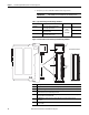
1756-IF8I Isolated Analog Input Module Chapter 3 Field-side Circuit Diagrams The following diagrams show the field-side circuitry for the 1756-IF8I module. Figure 6 - 1756-IF8I Module Field-side Circuit with Voltage Input IN_x/V 7500 Ω 1 μA Pullup 20 Ω + 1000 Ω IN_x/I/SRC Voltage Source 0.01 μF PGA – 1000 Ω 0.01 μF RTN-x A/D Converter 55 Ω 0.1 μF 0.01 μF 2.5V Vref 0.
Chapter 3 1756-IF8I Isolated Analog Input Module Figure 8 - 1756-IF8I Module Field-side Circuit with the Module Sourcing the Current Input Loop 7500 Ω IN_x/I/SRC +18V +18V IN_x/V Current Limit 20 Ω Current Limit + 0.01 μF 4…20 mA Transmitter 25 Ω 1000 Ω i_sense 0.01 μF – 24.9 Ω PGA A/D Converter 1000 Ω RTN-x 55 Ω 0.1 μF 0.01 μF 60 Rockwell Automation Publication 1756-UM540A-EN-P - May 2014 2.5V Vref 0.
1756-IF8I Isolated Analog Input Module Wire the 1756-IF8I Module Chapter 3 This section shows how to wire the 1756-IF8I module for current and voltage input types. Figure 9 - 1756-IF8I Module Wiring Diagram -Current Mode with External Loop Power In this wiring diagram, an external, user-provided power supply provides 24V DC loop power. IMPORTANT IMPORTANT: Remember the following: • If separate power sources are used, do not exceed the specific isolation voltage.
Chapter 3 1756-IF8I Isolated Analog Input Module Figure 10 - 1756-IF8I Module Wiring Diagram -Current Mode with Internal Loop Power IMPORTANT IMPORTANT: Remember the following: • If separate power sources are used, do not exceed the specific isolation voltage. For more information on module specifications, see the 1756 ControlLogix I/O Specifications Technical Data, publication 1756-TD002. • Place additional loop devices, for example, strip chart recorders, at either ‘A’ location in the current loop.
1756-IF8I Isolated Analog Input Module Chapter 3 Figure 11 - 1756-IF8I Module Wiring Diagram - Voltage Mode IMPORTANT: If separate power sources are used, do not exceed the specific isolation voltage. For more information on module specifications, see the 1756 ControlLogix I/O Specifications Technical Data, publication 1756-TD002.
Chapter 3 1756-IF8I Isolated Analog Input Module Fault and Status Reporting The 1756-IF8I module multicasts fault and status data with channel data to the owner and listening controllers. The data is returned via module tags that you can monitor in your Logix Designer application. With some exceptions, as noted in the following table, the 1756-IF8I module provides the fault and data status in a channel-centric format.
Chapter 4 1756-IRT8I Combined Temperature-sensing Isolated Analog Module Topic Page 1756-IRT8I Module Features 65 Module Block and Circuit Diagrams 87 Wire the 1756-IRT8I Module 89 Fault and Status Reporting 92 The 1756-IRT8I module has eight isolated channels. Each channel supports connection to the following input types: • RTD, both 3-wire and 4-wire • Thermocouple mV devices The module provides 24-bit data resolution. Additional features are described in this chapter.
Chapter 4 1756-IRT8I Combined Temperature-sensing Isolated Analog Module Multiple Input Ranges The 1756-IRT8I module offers multiple input ranges. The input type and sensor type selections determine the available ranges. The following table describes this module’s input ranges in relation to the sensor type. If a single range is listed in the Input Range column, the programming application automatically selects the range used with the previously listed sensor type.
1756-IRT8I Combined Temperature-sensing Isolated Analog Module Chapter 4 Notch Filter The notch filter is a built-in feature of the Analog-to-Digital convertor (ADC) that removes line noise in your application for each channel. The removal of line noise is also known as noise immunity. The notch filter attenuates the input signal at the specified frequency. That is, the filter reduces the amplitude of the signal with minimal signal distortion.
Chapter 4 1756-IRT8I Combined Temperature-sensing Isolated Analog Module Relationship between Noise Rejection Level and RPI Setting The 1756-IRT8I module offers two levels of line noise rejection. Each level has a filter associated with it. The module automatically determines which filter is used based on the notch filter setting and RPI rate. A trade-off exists between sampling speed and level of noise rejection: • The faster the sampling speed, the less noise rejection.
1756-IRT8I Combined Temperature-sensing Isolated Analog Module Chapter 4 For example, if your application requires a Notch Filter setting of 50 Hz, the module’s minimum RPI rate is 20.1 ms. In this case, sampling speed is more important than noise rejection. The module automatically uses a SINC^1 filter. If your application requires a Notch Filter setting of 50 Hz and the greater level of noise rejection provided by a SINC^3 filter, the minimum RPI rate is 60.1 ms.
Chapter 4 1756-IRT8I Combined Temperature-sensing Isolated Analog Module Underrange/Overrange Detection This feature detects when a temperature-measuring input module is operating beyond limits set by the input range. For example, if you are using the 1756-IRT8I module in the 2…1000 Ω input range and the module resistance increases to 1050 Ω, the overrange detection detects this condition.
1756-IRT8I Combined Temperature-sensing Isolated Analog Module Chapter 4 Digital Filter The digital filter smooths input data noise transients on each input channel. This value specifies the time constant for a digital first order lag filter on the input. It is specified in units of milliseconds. A value of 0 disables the filter. The digital filter equation is a classic first order lag equation.
Chapter 4 1756-IRT8I Combined Temperature-sensing Isolated Analog Module Process Alarms Process alarms alert you when the module has exceeded configured high or low limits for each channel. These are set at four, user-configurable, alarm trigger points: • High high • High • Low • Low low You can enable or disable Process Alarms individually via the Output tags for each channel. When a module is added to your Logix Designer application project and tags are created, the Alarms are disabled by default.
1756-IRT8I Combined Temperature-sensing Isolated Analog Module Chapter 4 Alarm Deadband You can configure an alarm deadband to work with these alarms. The deadband lets the process alarm status bit remain set, despite the alarm condition disappearing, as long as the input data remains within the deadband of the process alarm. The following graphic shows input data that sets each of the four alarms at some point during module operation.
Chapter 4 1756-IRT8I Combined Temperature-sensing Isolated Analog Module Rate Alarm The rate alarm triggers if the rate of change between input samples for each channel exceeds the specified trigger point for that channel. The actual rate of change for the last sample is returned in the Ch[x].RateOfChange input tag of each channel. EXAMPLE In normal scaling in Celsius, if you configure a channel’s rate alarm to 100.
1756-IRT8I Combined Temperature-sensing Isolated Analog Module Chapter 4 10 Ohm Copper Offset With this feature, you can compensate for a small offset error in a 10 ohm copper RTD. The channel must be connected to the 10 Ohm CU 427 Sensor Type to use this feature. The offset value is indicated in units of 0.01 Ohms. You can set the 10 Ohm copper offset in either of the following ways: • On the Configuration tab of the Module Properties dialog box. In this case, valid values are from -0.99…0.99.
Chapter 4 1756-IRT8I Combined Temperature-sensing Isolated Analog Module Because these modules can each be used in various applications, differences exist when a wire off condition is detected in each application. The table lists the differences that occur when a wire off condition occurs in various applications.
1756-IRT8I Combined Temperature-sensing Isolated Analog Module Chapter 4 Temperature Units You can use the following temperature units with your 1756-IRT8I module: • Celsius • Kelvin • Fahrenheit • Rankine Each channel is individually configurable for its temperature units. To see where to set the Temperature Units, see page 127. Sensor Types This module supports multiple sensor types with the available selections dictated by the input type configuration.
Chapter 4 1756-IRT8I Combined Temperature-sensing Isolated Analog Module Sensor Type Temperature Limits Sensor type temperature limits are determined by your choice of Input Type, Sensor Type, and Temperature Units. IMPORTANT When you make the configuration choices listed previously, the Scaling parameters are automatically set on the Configuration tab of the Module Properties dialog box and cannot be changed in the software. The Low Signal value equals the Low Engineering value.
1756-IRT8I Combined Temperature-sensing Isolated Analog Module Chapter 4 The following table lists temperature range limits on the 1756-IRT8I module.
Chapter 4 1756-IRT8I Combined Temperature-sensing Isolated Analog Module Table 12 - Temperature Limits for RTD and Thermocouple Sensor Types 80 Input Type Sensor Type Temperature Range Limits Thermocouple (mV) TC Type B 21…1820 °C 68…3308 °F 293…2093 °K 528…3768 °R TC Type C 0…2320 °C 32…4208 °F 273…2593 °K 492…4668 °R TC Type D 0…2320 °C 32…4208 °F 273…2593 °K 492…4668 °R TC Type E -270…1000 °C -454…1832 °F 3…1273 °K 6…2292 °R TC Type J -210…1200 °C -346…2192 °F 63…1473 °K 114…2652 °R TC
1756-IRT8I Combined Temperature-sensing Isolated Analog Module Chapter 4 Thermocouple Wire Length Compensation Wires connecting a thermocouple to the 1756-IRT8I module have an intrinsic resistance that can negatively impact the module’s accuracy. The wire length and gauge are directly related to resistance level and, by extension, to impact on the module accuracy. The longer the wire length, the greater the resistance, the greater the possible negative impact on module accuracy.
Chapter 4 1756-IRT8I Combined Temperature-sensing Isolated Analog Module For example, if you have 12 input devices connected to two 1756-IRT8I modules and one 1756-IF8I module in the same chassis, or different chassis synchronized to the same CIP Sync TimeMaster, use Synchronized Sampling to take a snapshot of the input data available at each input at a single moment in time. The following conditions must exist to use this feature: • A 1588 CIP Sync Time Master is configured for the chassis.
1756-IRT8I Combined Temperature-sensing Isolated Analog Module Chapter 4 The thermoelectric effect alters the input signal and must be compensated for to measure temperatures accurately. To accurately compensate the input signal from your module, you must use a cold junction compensation (CJC) sensor to account for the increased voltage. IMPORTANT CJC sensors are only required with use of the Thermocouple input type and when channel wiring is connected via an RTB.
Chapter 4 1756-IRT8I Combined Temperature-sensing Isolated Analog Module Connecting a CJC via a Removable Terminal Block When using an RTB, if you choose to connect CJC sensors to your module, you must connect a CJC sensor at the top of the RTB and one at the bottom of the RTB. IMPORTANT Remember the following: • Connect the white end of the CJC sensor to the even-numbered terminals. For CJ 0, connect the white end to terminal 2. For CJ 1, connect the white end to terminal 36.
1756-IRT8I Combined Temperature-sensing Isolated Analog Module Chapter 4 Connecting a Cold Junction Sensor via an Interface Module The IFMs use an isothermal bar to maintain a steady temperature at all module terminations. When using the IFM, we recommend that you mount it so that the black anodized aluminum bar is in the horizontal position. When using an IFM, do not connect a CJC sensor to the module because it is built into the IFM.
Chapter 4 1756-IRT8I Combined Temperature-sensing Isolated Analog Module IMPORTANT Consider the following before disabling cold junction compensation: • We recommend that you do not disable the cold junction disable option. Typically, this option is used only in systems that have no thermoelectric effect, such as test equipment in a controlled lab. • The Cold Junction Disable box on the Module Properties Configuration tab disables cold junction compensation on all module channels.
1756-IRT8I Combined Temperature-sensing Isolated Analog Module Module Block and Circuit Diagrams Chapter 4 The graphics in this section show the 1756-IRT8I module’s block diagrams and field-side circuit diagrams.
Chapter 4 1756-IRT8I Combined Temperature-sensing Isolated Analog Module Field-side Circuit Diagrams The following diagrams show the field-side circuitry for the 1756-IRT8I module. Figure 14 - 1756-IRT8I Module Field-side with 3-wire RTD Input I exc 600 μA IN_x/RTD D I exc 600 μA 1000 Ω 10 Ω IN_x(+)/A 0.01 μF PGA RTD 1000 Ω 0.01 μF 10 Ω IN_x(-)/B A/D Converter 2.5V Vref 0.1 μF 0.01 μF 0.
1756-IRT8I Combined Temperature-sensing Isolated Analog Module Chapter 4 Figure 16 - 1756-IRT8I Module Field-side Circuit with Thermocouple Input IN_x/RTD D 1000 Ω 10 Ω IN_x(+)/A 0.01 μF PGA TC 1000 Ω 0.01 μF 10 Ω IN_x(-)/B 2.5V Vref 0.1 μF 0.01 μF IN_x/RTD C Wire the 1756-IRT8I Module A/D Converter 0.01 μF The following graphics show wiring examples for the 1756-IRT8I module used with RTD and thermocouple input types.
Chapter 4 1756-IRT8I Combined Temperature-sensing Isolated Analog Module Figure 18 - 1756-IRT8I Module Wiring Diagram - 4-wire RTD Input IMPORTANT: Remember the following: • If separate power sources are used, do not exceed the specific isolation voltage. For more information on module specifications, see the 1756 ControlLogix I/O Specifications Technical Data, publication 1756-TD002. • Terminals 1, 2, 35, and 36 are not used in RTD applications.
1756-IRT8I Combined Temperature-sensing Isolated Analog Module Chapter 4 Figure 19 - 1756-IRT8I Module Wiring Diagram - Thermocouple Input IMPORTANT: Remember the following: • Connect the white end of the CJC sensor to the evennumbered terminal., and connect the orange end of the CJC sensor to the odd-numbered terminals.
Chapter 4 1756-IRT8I Combined Temperature-sensing Isolated Analog Module Fault and Status Reporting The 1756-IRT8I module multicasts fault and status data with channel data to the owner and listening controllers. The data is returned via module tags that you can monitor in your Logix Designer application. With some exceptions, as noted in the following table, the 1756-IRT8I module provides the fault and data status in a channel-centric format.
Chapter 5 1756-OF8I Isolated Analog Output Module Topic Page 1756-OF8I Module Features 98 Module Block and Output Circuit Diagrams 98 Drive Different Loads with the 1756-OF8I Module 100 Wire the 1756-OF8I Module 100 Fault and Status Reporting 102 The 1756-OF8I module has eight isolated channels. Each channel supports the following output types: • Current • Voltage The module provides 16-bit resolution. Additional features are described in this chapter.
Chapter 5 1756-OF8I Isolated Analog Output Module Multiple Output Ranges The 1756-OF8I module offers multiple output ranges that are dictated by channel configuration choices. The output type selection determines the available ranges. Table 14 - Channel Output Ranges Output Type Output Range Current (mA) 0…20 mA Voltage (V) Any of the following: • -10…10V • 0…5V • 0…10V To see where to select the output range, see page 127.
1756-OF8I Isolated Analog Output Module Chapter 5 Ramping/Rate Limiting Ramping limits the speed at which an analog output signal can change. This prevents fast transitions in the output from damaging the devices that an output module controls. Ramping is also known as rate limiting. The table describes the types of ramping that are possible. Ramping type Description Run mode ramping When the module is in Run mode, ramping occurs to all new output values at the MaxRampRate.
Chapter 5 1756-OF8I Isolated Analog Output Module Clamping/Limiting Clamping limits the output from the analog module to remain within a range configured by the controller, even when the controller commands an output outside that range. This safety feature sets a high clamp and a low clamp.
1756-OF8I Isolated Analog Output Module Chapter 5 Clamp/Limit Alarms This function works directly with clamping. When a module receives a data value from the controller that exceeds clamping limits, it applies signal values to the clamping limit but also sends a status bit to the controller notifying it that the value sent exceeds the clamping limits.
Chapter 5 1756-OF8I Isolated Analog Output Module Module Block and Output Circuit Diagrams The graphics in this section show the 1756-OF8I module’s block diagrams and input circuit diagrams.
1756-OF8I Isolated Analog Output Module Chapter 5 Field-side Circuit Diagrams The following diagrams show the field-side circuitry for the 1756-OF8I module. Figure 21 - 1756-OF8I Module Field-side Circuit with Current Output +V Power Supply OUT_x/V D/A Converter Current Amplifier 46 Ω Iout 5V Vref OUT_x/I 0.0022 μF 0.047 μF Current Output Device 0…1000 Ω -13V RTN-x Figure 22 - 1756-OF8I Module Field-side Circuit with Voltage Output 4640 Ω +13V Vsense 21 Ω D/A Converter OUT_x/V Vout 0.
Chapter 5 1756-OF8I Isolated Analog Output Module Drive Different Loads with the 1756-OF8I Module When the 1756-OF8I module operates with a Current output load, each channel automatically adjusts its output power for 0…1000 ohm loads. The module’s 24V backplane current requirements vary based on load. For more information the module’s 24V current requirements, see the 1756 ControlLogix I/O Specifications Technical Data, publication 1756-TD002.
1756-OF8I Isolated Analog Output Module Chapter 5 Figure 24 - 1756-OF8I Module Wiring Diagram - Voltage Output Type IMPORTANT: Remember the following: • If separate power sources are used, do not exceed the specific isolation voltage. For more information on module specifications, see the 1756 ControlLogix I/O Specifications Technical Data, publication 1756-TD002. • Place additional devices anywhere in the loop.
Chapter 5 1756-OF8I Isolated Analog Output Module Fault and Status Reporting The 1756-OF8I module multicasts fault and status data with channel data to the owner and listening controllers. The data is returned via module tags that you can monitor in your Logix Designer application. With some exceptions, as noted in the following table, the 1756-OF8I module provides the fault and data status in a channel-centric format.
Chapter 6 Install ControlLogix Isolated Analog I/O Modules Topic Page Install the I/O Module 106 Key the Removable Terminal Block 108 Connect Wiring 109 Assemble the RTB and the Housing 114 Choose Extended-depth Housing 115 Install the Removable Terminal Block 117 Remove the Removable Terminal Block 118 Remove the Module from the Chassis 119 This chapter assumes that you have already installed a 1756 ControlLogix chassis and power supply. If not, do so before proceeding.
Chapter 6 Install ControlLogix Isolated Analog I/O Modules North American Hazardous Location Approval The following information applies when operating this equipment in hazardous locations. Products marked "CL I, DIV 2, GP A, B, C, D" are suitable for use in Class I Division 2 Groups A, B, C, D, Hazardous Locations and nonhazardous locations only. Each product is supplied with markings on the rating nameplate indicating the hazardous location temperature code.
Install ControlLogix Isolated Analog I/O Modules Chapter 6 WARNING: • This equipment shall be mounted in an ATEX-certified enclosure with a minimum ingress protection rating of at least IP54 (as defined in IEC60529) and used in an environment of not more than Pollution Degree 2 (as defined in IEC 60664-1) when applied in Zone 2 environments. The enclosure must have a tool-removable cover or door. • This equipment shall be used within its specified ratings defined by Rockwell Automation.
Chapter 6 Install ControlLogix Isolated Analog I/O Modules Install the I/O Module You can install or remove a module while chassis power is applied.Removal and Insertion Under Power (RIUP) provides the flexibility to maintain modules without having to stop production. WARNING: When you insert or remove the module while backplane power is on, an electrical arc can occur. This could cause an explosion in hazardous location installations.
Install ControlLogix Isolated Analog I/O Modules Chapter 6 Complete these steps to install an I/O module. 1. Align the circuit board with the top and bottom chassis guides. Printed Circuit Board 20861-M 2. Slide the module into the chassis until the module locking tab clicks.
Chapter 6 Install ControlLogix Isolated Analog I/O Modules Key the Removable Terminal Block Key the removable terminal block (RTB) to prevent inadvertently connecting the wrong wiring in the RTB to your module. Wedge- and U-shaped bands are manually inserted into the RTB and module. This process hinders a wired RTB from being accidentally inserted into a module that does not match the positioning of the respective tabs. Key positions on the module that correspond to unkeyed positions on the RTB.
Install ControlLogix Isolated Analog I/O Modules Connect Wiring Chapter 6 Connect wiring to the module with an RTB or a Bulletin 1492 pre-wired Analog Interface Module (AIFM). This section describes how to wire the module with an RTB. If you are using an AIFM to connect wiring, see the documentation for that product.
Chapter 6 Install ControlLogix Isolated Analog I/O Modules Connect the Grounded End of the Cable Before wiring the RTB, you must connect the ground wiring. IMPORTANT We recommend that you ground the following ControlLogix isolated analog module shield and drain wires at the field-side: • 1756-OF8I • 1756-IRT8I • 1756-IF8I on points that use the non-sourcing current/voltage functionality If you cannot ground the module shield and drain wires at field-side, ground them at an earth ground on the chassis.
Install ControlLogix Isolated Analog I/O Modules Chapter 6 5. Connect the drain wire to a chassis mounting tab. Use any chassis mounting tab that is designated as a functional signal ground. The functional earth ground symbol appears near the tab. 4 m or 5 m (#10 or #12) Star Washer Chassis Mounting Tab Functional Earth Ground Symbol Drain Wire with Ground Lug 4 m or 5 m (#10 or #12) Star Washer Phillips Screw and Star Washer (or SEM Screw) 20918-M 6.
Chapter 6 Install ControlLogix Isolated Analog I/O Modules RTB Types Each RTB comes with housing. The following RTB types work with ControlLogix isolated analog I/O modules: • Cage Clamp RTB - Catalog Number 1756-TBCH • Spring Clamp RTB - Catalog Number 1756-TBS6H ATTENTION: Consider the following when using the 1756-TBCH RTB: • Do not wire more than two 0.33...1.3 mm2 (22...16 AWG) conductors on any single terminal. • You can connect only one 2.1 mm2 (14 AWG) conductor to any single terminal.
Install ControlLogix Isolated Analog I/O Modules Chapter 6 Spring Clamp RTB - Catalog Number 1756-TBS6H 1. Strip 11 mm (7/16 in.) maximum length of wire. 2. Insert the screwdriver into the outer hole of the RTB to depress the springloaded clamp. 3. Insert the wire into the open terminal and remove the screwdriver. 4. Insert the wire into the open terminal and remove the screwdriver.
Chapter 6 Install ControlLogix Isolated Analog I/O Modules Assemble the RTB and the Housing Removable housing covers the wired RTB to protect wiring connections when the RTB is seated on the module. 1. Align the grooves at the bottom of each side of the housing with the side edges of the RTB. 2. Slide the RTB into the housing until it snaps into place.
Install ControlLogix Isolated Analog I/O Modules Choose Extended-depth Housing Chapter 6 There are two housing options available when wiring your ControlLogix isolated analog I/O module: • Standard-depth housing • Extended-depth housing When you order an RTB for your I/O module, you receive standard-depth housing. If your application uses heavy gauge wiring, you can order extended-depth housing. Extended-depth housing does not come with an RTB.
Chapter 6 Install ControlLogix Isolated Analog I/O Modules Cabinet Size Considerations with Extended-depth Housing When you use extended-depth housing, catalog number 1756-TBE, the I/O module depth is increased. The diagram shows the difference in depth between an I/O module using standard-depth housing and one using extended-depth housing. Dimensions are in mm (in.) 144.73 (5.698) 12.7 (0.5) 131.75 (5.187) 3.18 (0.
Install ControlLogix Isolated Analog I/O Modules Install the Removable Terminal Block Chapter 6 These steps show how to install the RTB onto the module to connect the wiring. WARNING: When you connect or disconnect the removable terminal block (RTB) with field-side power applied, an electrical arc can occur. This could cause an explosion in hazardous location installations. Be sure that power is removed or the area is nonhazardous before proceeding. ATTENTION: Shock hazard exists.
Chapter 6 Install ControlLogix Isolated Analog I/O Modules 2. Press quickly and evenly to seat the RTB on the module until the latches snap into place. 3. Slide the locking tab down to lock the RTB onto the module. 20854-M Remove the Removable Terminal Block If you need to remove the module from the chassis, you must first remove the RTB from the module. WARNING: When you insert or remove the module while backplane power is on, an electrical arc can occur.
Install ControlLogix Isolated Analog I/O Modules Chapter 6 Complete the following steps to remove the RTB. 1. Unlock the locking tab at the top of the module. 2. Open the RTB door by using the bottom tab. 3. Hold the spot marked PULL HERE and pull the RTB off the module. 20855-M IMPORTANT Remove the Module from the Chassis Do not wrap your fingers around the entire door. A shock hazard exists. Complete the following steps to remove a module from its chassis. 1.
Chapter 6 Install ControlLogix Isolated Analog I/O Modules Notes: 120 Rockwell Automation Publication 1756-UM540A-EN-P - May 2014
Chapter 7 Configure ControlLogix Isolated Analog I/O Modules Topic Page Create a New Module 122 Edit the Configuration 125 Copy Channel Configuration 134 View the Module Tags 136 IMPORTANT This chapter describes how to configure you module with Logix Designer application, version 21 and later. You can use the ControlLogix isolated analog I/O modules in RSLogix 5000 software projects as well.
Chapter 7 Configure ControlLogix Isolated Analog I/O Modules Create a New Module After you create a Logix Designer application project, complete the following steps to create a new module in the project. 1. Right-click I/O Configuration and choose New Module. 2. Select the module and click Create. 3. Click OK to accept the default major revision. TIP You can verify the module’s revision in RSLinx® Classic software. The New Module dialog box appears.
Configure ControlLogix Isolated Analog I/O Modules Chapter 7 4. On the General tab, name the module and make sure the Slot number in the configuration matches the physical slot number of the chassis housing the module. The Description field is optional. 5. Click OK to accept the module’s default configuration. The rest of this section describes how to change module configuration to work as needed in your system.
Chapter 7 Configure ControlLogix Isolated Analog I/O Modules Module Definition On the General tab, click Change … to access the Module Definition dialog box. The following parameters are available on the Module Definition dialog box: • Series - Module hardware series • Revision - Module firmware revision • Electronic Keying - For more information, see page 28. • Connection - For more information, see page 125.
Configure ControlLogix Isolated Analog I/O Modules Chapter 7 Connection Type The communication format determines the following for the module type you configure: • Available configuration parameters • Data type transferred between the module and the controller • Which tags are generated when configuration is complete The following table describes connection formats used with isolated analog I/O modules.
Chapter 7 Configure ControlLogix Isolated Analog I/O Modules Connection Tab The Connection tab lets you complete the following tasks: • Set the RPI rate. For more information the RPI, see page 14. • Inhibit the module. For more information on inhibiting the module, see page 26. • Configure whether a connection failure while the controller is in Run module causes a major or minor fault. The Module Fault area of the Connection tab is useful during module troubleshooting.
Configure ControlLogix Isolated Analog I/O Modules Chapter 7 Configuration Tab The fields on the Configuration tab are specific to the module type. The following are examples of tasks you complete via this tab: • Select an input or output type. • Select a module’s operating range. • Define scaling parameters. 1756-IF8I Module For information on this tab’s configurable parameters, see Chapter 3, 1756-IF8I Isolated Analog Input Module on page 45.
Chapter 7 Configure ControlLogix Isolated Analog I/O Modules 1756-IRT8I Module For information on this tab’s configurable parameters, see Chapter 4, 1756IRT8I Combined Temperature-sensing Isolated Analog Module on page 65. 1756-OF8I Module For information on this tab’s configurable parameters, see Chapter 5, 1756-OF8I Isolated Analog Output Module on page 93. IMPORTANT: Changes to the High Engineering and Low Engineering values do not automatically change the Clamp values on the Limit Configuration tab.
Configure ControlLogix Isolated Analog I/O Modules Chapter 7 Calibration Tab The Calibration tab lets you recalibrate the module. Calibration corrects any hardware inaccuracies on a module. IMPORTANT The isolated analog I/O modules do not require recalibration after operating in an application. For information on how to configure each module type, see Chapter 8, Calibrate the ControlLogix Isolated Analog I/O Modules on page 137.
Chapter 7 Configure ControlLogix Isolated Analog I/O Modules 1756-IRT8I Module 1756-OF8I Module 130 Rockwell Automation Publication 1756-UM540A-EN-P - May 2014
Configure ControlLogix Isolated Analog I/O Modules Chapter 7 Alarm Configuration Tab The fields on the Alarm Configuration tab are specific to the module type. The following are examples of tasks you complete via this tab: • Disable alarms. • Set alarm parameters. • Set rate limits. This tab is available only for input modules. 1756-IF8I Module For information on this tab’s configurable parameters, see Chapter 3, 1756-IF8I Isolated Analog Input Module on page 45.
Chapter 7 Configure ControlLogix Isolated Analog I/O Modules 1756-IRT8I Module For information on this tab’s configurable parameters, see Chapter 4, 1756IRT8I Combined Temperature-sensing Isolated Analog Module on page 65. CJ Configuration Tab The CJ Configuration tab is available with only the 1756-IRT8I module. You use this tab to configure the cold junction compensation option.
Configure ControlLogix Isolated Analog I/O Modules Chapter 7 Limit Configuration Tab The Limit Configuration tab is available with only the 1756-OF8I module. You use this tab to configure clamp limits and module ramping. IMPORTANT: Changes to the High Engineering and Low Engineering values on the Configuration tab do not change the Clamp values on this tab, when Clamp Limits are enabled.
Chapter 7 Configure ControlLogix Isolated Analog I/O Modules Copy Channel Configuration The Copy Channel Configuration feature lets you quickly and easily use the same configuration across multiple channels on a module. You can configure channel parameters on Module Properties dialog box and copy them to other channels.
Configure ControlLogix Isolated Analog I/O Modules Chapter 7 4. Click Copy Channel Configuration. 5. Click the channels to which you want to copy channel configuration and click OK. The configuration is copied to the other channels. 6. Click OK or Apply for the new channel configuration to take effect. TIP If desired, you can apply configuration changes to the first channel, as described in step 3, before moving to the next step and copying channel configuration.
Chapter 7 Configure ControlLogix Isolated Analog I/O Modules View the Module Tags When you create a module, the Logix Designer application creates a set of tags that you can view in the Tag Editor. Each configured feature on your module has a distinct tag that is available for use in the controller’s programming logic. Complete these steps to access a module’s tags. 1. In the Controller Organizer, right-click Controller Tags and choose Monitor Tags. The Controller Tags dialog box appears with data. 2.
Chapter 8 Calibrate the ControlLogix Isolated Analog I/O Modules Topic Page Difference between Calibrating an Input Module and an Output Module 138 Calibrate the Input Modules 139 Calibrate the Output Module 152 The ControlLogix isolated analog I/O modules are calibrated during the manufacturing process. Each module’s accuracy remains high throughout its lifespan. IMPORTANT You are not required to calibrate the module at any point in its lifespan.
Chapter 8 Calibrate the ControlLogix Isolated Analog I/O Modules Difference between Calibrating an Input Module and an Output Module Although the purpose of calibrating analog modules is the same for input and output modules, to improve the module’s accuracy and repeatability, the procedures involved differs for each: • When you calibrate input modules, you use current, voltage, or ohms reference signals to send a signal to the module to calibrate it.
Calibrate the ControlLogix Isolated Analog I/O Modules Chapter 8 Calibrate in Program Mode Your project must be online with the controller to calibrate ControlLogix isolated analog I/O modules. You can calibrate in the following conditions: • The controller in Program mode--either Remote Program or Program mode. We recommend that your module be in Program mode and not be actively controlling a process when you calibrate it.
Chapter 8 Calibrate the ControlLogix Isolated Analog I/O Modules Calibrate the 1756-IF8I Module For Voltage Input Type During voltage calibration, 0.0V and +10.0V external references are applied to the module’s channels. The module records the deviation from these reference values and stores it as calibration constants in the module’s firmware.
Calibrate the ControlLogix Isolated Analog I/O Modules Chapter 8 4. On the Configuration tab, make sure the Input Type for each channel to be calibrated is set to Voltage (V). The input range selection does not impact calibration. 5. On the Calibration tab, click Start Calibration. 6. When the warning appears, click OK. 7. Select the channels to be calibrated and click Next.
Chapter 8 Calibrate the ControlLogix Isolated Analog I/O Modules The Attach Low Reference Voltage Signals dialog box appears, as shown below. It indicates the channels are calibrated for a low reference and the range of the calibration. 8. Set the calibrator for the low reference and apply it to the module. 9. Click Next. The Group Low Reference Results dialog box indicates the status of each channel after calibrating for a low reference. 10. If channels are OK, click Next.
Calibrate the ControlLogix Isolated Analog I/O Modules Chapter 8 The Attach High Reference Voltage Signals dialog box appears, as shown below. It indicates the channels are calibrated for a high reference and the range of the calibration. 11. Set the calibrator for the high reference voltage and apply it to the module. 12. Click Next. The Group High Reference Results dialog box indicates the status of each channel after calibrating for a high reference. 13. If channels are OK, click Next.
Chapter 8 Calibrate the ControlLogix Isolated Analog I/O Modules Calibrate the 1756-IRT8I Module You can calibrate the 1756-IRT8I module for use with the following input types: • RTD (Ohms) - 3 and 4 Wire types • Thermocouple (mV) Calibrate the 1756-IRT8I Module for an RTD Input Type The 1756-IRT8I uses two precision resistors to calibrate the channels in ohms.
Calibrate the ControlLogix Isolated Analog I/O Modules Chapter 8 3. On the Configuration tab, make sure the Input Type for each channel to be calibrated is set to the same RTD input type. The sensor type selection does not impact calibration. 4. On the Calibration tab, click Start Calibration. 5. When the warning appears, click OK. 6. Select the channels to be calibrated and click Next.
Chapter 8 Calibrate the ControlLogix Isolated Analog I/O Modules The Attach Low Reference Ohms Sources dialog box appears, as shown below. It indicates the channels are calibrated for a low reference and the range of the calibration. 7. Connect a 1 Ω precision resistor to all module channels being calibrated. IMPORTANT After you connect the precision resistor, we recommend that you wait for a minimum of two minutes before proceeding to the next task to obtain the highest calibration accuracy. 8.
Calibrate the ControlLogix Isolated Analog I/O Modules Chapter 8 The Attach High Reference Ohms Sources dialog box appears. It indicates the channels are calibrated for a high reference and the range of the calibration. 10. Connect a 487 Ω precision resistor to all module channels being calibrated. IMPORTANT After you connect the precision resistor, we recommend that you wait for a minimum of two minutes before proceeding to the next task to obtain the highest calibration accuracy. 11. Click Next.
Chapter 8 Calibrate the ControlLogix Isolated Analog I/O Modules 13. When the Calibration Completed dialog box appears, click Finish. Calibrate the 1756-IRT8I for a Thermocouple Input Type IMPORTANT Channels configured for Thermocouple inputs perform a wire resistance selfcalibration when the module power is cycled. Follow these steps to calibrate your module. 1. Connect your voltage calibrator to all module channels being calibrated. 2. Go online with your project. 3.
Calibrate the ControlLogix Isolated Analog I/O Modules Chapter 8 5. On the Calibration tab, click Start Calibration. 6. When the warning appears, click OK. 7. Select the channels to be calibrated and click Next. The Attach Low Reference Voltage Signals dialog box appears, as shown below. It indicates the channels are calibrated for a low reference and the range of the calibration.
Chapter 8 Calibrate the ControlLogix Isolated Analog I/O Modules 8. Set the calibrator for the low reference and apply it to the module. 9. Click Next. The Group Low Reference Results dialog box appears, as shown below. It indicates the status of each channel after calibrating for a low reference. 10. If channels are OK, click Next. If any channel reports an error, return to step 8 and click Retry until the status is OK. If the error persists indefinitely, click Stop to exit calibration.
Calibrate the ControlLogix Isolated Analog I/O Modules Chapter 8 11. Set the calibrator for the high reference voltage and apply it to the module. 12. Click Next. The Group High Reference Results dialog box indicates the status of each channel after calibrating for a high reference. 13. If channels are OK, click Next. If any channel reports an error, return to step 11 and click Retry until the status is OK. If the error persists indefinitely, click Stop to exit calibration.
Chapter 8 Calibrate the ControlLogix Isolated Analog I/O Modules Calibrate the Output Module You can calibrate the 1756-OF8I module for use with the following output types: • Current (mA) • Voltage (V) IMPORTANT This section shows how to calibrate the 1756-OF8I modules for use with only current outputs. The calibration process is generally the same if you calibrate the module for use with voltage inputs except for the following differences: • You connect a voltage meter to the module.
Calibrate the ControlLogix Isolated Analog I/O Modules Chapter 8 4. On the Configuration tab, make sure the Output Type for each channel to be calibrated is set to Current (mA). 5. On the Calibration tab, click Start Calibration. 6. When the warning appears, click OK. 7. Select the channels to be calibrated and click Next.
Chapter 8 Calibrate the ControlLogix Isolated Analog I/O Modules The Output Reference Signals dialog box appears. It indicates the channels are calibrated for a low reference and the calibration range. 8. Click Next. The Measure and Record Values dialog box appears. 9. For each channel being calibrated, use your current meter to measure the reference value of each channel individually. 10. In the Recorded Reference (mA) column record the measured value for each channel that was recorded and click Next.
Calibrate the ControlLogix Isolated Analog I/O Modules Chapter 8 The Output Reference Signals dialog box appears, as shown below. It indicates the channels are calibrated for a high reference and the calibration range. 12. Click Next. The Measure and Record Values dialog box appears. 13. For each channel being calibrated, use your current meter to measure the reference value of each channel individually. 14.
Chapter 8 Calibrate the ControlLogix Isolated Analog I/O Modules The Group High Reference Results dialog box indicates the status of each channel. If the status is not OK for any channels, repeat the calibration process. If the error persists indefinitely, click Stop to exit calibration. The channel remains calibrated to the accuracy level achieved at factory calibration. 15. Click Next. The Calibration Completed dialog box indicates the status of each channel. 16. Click Finish.
Chapter 9 Troubleshoot Your Module Topic Page Status Indicators for the 1756-IF8I Module 157 Status Indicators for the 1756-IRT8I Module 158 Status Indicators for the 1756-OF8I Module 159 Use Logix Designer Application for Troubleshooting 160 Troubleshoot Incorrect Readings on the Module 162 ControlLogix isolated analog I/O module have status indicators on the front of the module that are used to monitor module operation.
Chapter 9 Troubleshoot Your Module FLT Status Indicators for the 1756-IRT8I Module Off The channel is operating as expected. Steady red • The channel is faulted.Possible causes of the fault include: – Underrange/overrange detection – Triggered process alarm – Triggered rate alarm – Wire off detection – Calibration fault For more information on these causes see Chapter 3, 1756-IF8I Isolated Analog Input Module on page 45 Flashing red One of the following: • The channel is faulted.
Troubleshoot Your Module Status Indicators for the 1756-OF8I Module Chapter 9 The following graphic shows the status indicators used with 1756-OF8I module. ANALOG OUPUT ST O K FLT The following table describes the status indicators. Indicator Status Description OK Steady green The module is in a normal operating state in Run mode. Flashing green The module passed internal diagnostics and is not actively controlled or the connection is open and the controller is in Program mode.
Chapter 9 Troubleshoot Your Module Use Logix Designer Application for Troubleshooting The Logix Designer application indicates fault conditions in the following ways: • Warning signal on the main screen next to the module - This occurs when the connection to the module is broken. • Message in a screen’s status line On the Module Info tab, in the Status section, the Major and Minor Faults are listed along with the Internal State of the module.
Troubleshoot Your Module Chapter 9 • Notification in the Tag Editor - General module faults are also reported in the Tag Editor. Diagnostic faults are reported only in the Tag Editor. The Value field indicates a fault with the number 1. Fault Type Determination When you are monitoring a module’s configuration properties in the Logix Designer application and receive a Communication fault message, the Connection tab indicates the type of fault under Module Fault.
Chapter 9 Troubleshoot Your Module Troubleshoot Incorrect Readings on the Module Incorrect temperature, current or voltage readings on temperature-sensing and current/voltage I/O modules are often considered to be the result of a module needing to be calibrated. This is typically not the case. ControlLogix isolated analog I/O modules are calibrated before shipment from the factory and maintain a high degree of module accuracy throughout their lifespan.
Troubleshoot Your Module Chapter 9 2. Check the module wiring to verify the following: – The wiring is correct. – The wiring is intact. – The CJC sensors, if being used, are installed correctly. IMPORTANT Remember, if you choose to use CJC sensors with the 1756-IRT8I module, you must use the sensors at both connection positions, that is, the top and bottom of the module. You cannot use only one CJC sensor with the module.
Chapter 9 Troubleshoot Your Module If the previously listed tasks fail to resolve your issue with incorrect temperature readings on your module, use the following table. Table 16 - 1756-IRT8I Module - Troubleshoot Incorrect Temperature Readings Possible Cause of Incorrect Reading Description Recommended Action Open circuit A thermocouple reading maximum (upscale) usually means that there is an open circuit condition.
Troubleshoot Your Module Chapter 9 1756-IRT8I Module - Incorrect RTD Readings To determine the cause of the incorrect reading, first determine the nature of the incorrect reading. For example, the module can perform as follows: • The module always reads maximum. • The module always reads minimum. • The module reads erratically (data jumping around). • The module reads with an offset over the entire range. First, complete the following tasks. 1.
Chapter 9 Troubleshoot Your Module If the previously listed tasks fail to resolve your issue with incorrect RTD readings on your module, use the following table. Table 17 - 1756-IRT8I Module - Troubleshoot Incorrect RTD Readings Possible Cause of Incorrect Reading Description Recommended Action Wire Off When using a 3-wire RTD device and any of the following: • One wire is disconnected from any of the channel’s terminals.
Troubleshoot Your Module Chapter 9 Table 17 - 1756-IRT8I Module - Troubleshoot Incorrect RTD Readings Possible Cause of Incorrect Reading Description Recommended Action Electrical noise Erratic readings, that is, data fluctuating more than is typical, are a cause of noise. An oscilloscope shows the magnitude of noise. • Disconnect all but one RTD to see if channels are affecting each other, that is, there is bleed-over. • Eliminate or suppress the effect of noise.
Chapter 9 Troubleshoot Your Module 1756-IF8I Module - Incorrect Input Voltage/Current Readings To determine the cause of the incorrect reading, first determine the nature of the incorrect reading. For example, the module can perform as follows: • The module always reads maximum. • The module always reads minimum/zero/negative. • The module reads voltage/current erratically (data jumping around). • The module reads with an offset over the entire range. First, complete the following tasks. 1.
Troubleshoot Your Module Chapter 9 If the previously listed tasks fail to resolve your issue with incorrect voltage or current readings on your module, use the following table. Table 18 - 1756-IF8I Module - Troubleshoot Incorrect Input Voltage/Current Readings Possible Cause of Incorrect Reading Description Recommended Action Open wire When the module is used in Voltage mode and any of the following: • A wire is disconnected from the module. • A 4-wire transmitter has no power applied.
Chapter 9 Troubleshoot Your Module Table 18 - 1756-IF8I Module - Troubleshoot Incorrect Input Voltage/Current Readings Possible Cause of Incorrect Reading Description Recommended Action DC signal on top of the input signal Offset readings can be caused by a DC signal riding on top of the input signal. An oscilloscope shows the magnitude of the offset. Disconnect all but one input to see if channels are affecting each other, that is, there is bleed-over.
Troubleshoot Your Module Chapter 9 1756-OF8I Module - Incorrect Output Voltage/Current Readings To determine the cause of the incorrect reading, first determine the nature of the incorrect reading. For example, the module can perform as follows: • The module always outputs maximum. • The module always outputs zero. • The module outputs a smaller value than expected. • The module outputs erratic voltage/current data. First, complete the following tasks. 1.
Chapter 9 Troubleshoot Your Module If the previously listed tasks fail to resolve your issue with incorrect voltage or current readings on your module, use the following table. Table 19 - 1756-OF8I Module - Troubleshoot Incorrect Input Voltage/Current Readings Possible Cause of Incorrect Output Description Recommended Action Open wire One of the following: • The load does not respond to the applied voltage/current output. • A wire is disconnected from the module.
Appendix A Isolated Analog I/O Module Tag Definitions Topic Page Access the Tags 173 1756-IF8I Module Tags 175 1756-IRT8I Module Tags 182 1756-OF8I Module Tags 191 Module tags are created when you add a module to the Logix Designer application project. The set of tags associated with any module depends on the module type and the connection type. There are three sets of tags for each module: • Configuration • Input • Output Access the Tags You can view tags from the Tag Editor.
Appendix A Isolated Analog I/O Module Tag Definitions 3. Open the tags as needed to view specific tags.
Isolated Analog I/O Module Tag Definitions Appendix A This section describes the tags associated with the 1756-IF8I module. 1756-IF8I Module Tags IMPORTANT Each application’s series of tags varies but no input module application contains any tags that are not listed here. Configuration Tags The following table describes the Configuration tags associated with the 1756-IF8I module. Table 20 - 1756-IF8I Module - Configuration Tags Tag Name Size Definition Valid Values Ch[x].
Appendix A Isolated Analog I/O Module Tag Definitions Table 20 - 1756-IF8I Module - Configuration Tags Tag Name Size Definition Valid Values Ch[x].RateAlarmLimit REAL Rate of change in Engineering Units/Second If the absolute value of the change between samples divided by the sample time exceeds this value, the I.Ch[x].RateAlarm tag is sets. Any positive value 0.0 = default (This value represents no change between samples.) Ch[x].
Isolated Analog I/O Module Tag Definitions Appendix A Input Tags The following table describes the Input tags associated with the 1756-IF8I module. Table 21 - 1756-IF8I Module - Input Tags Tag Name Size Definition Valid Values Fault DINT Standard Analog Fault mask – controller sets all 32 bits on connection loss.
Appendix A Isolated Analog I/O Module Tag Definitions Table 21 - 1756-IF8I Module - Input Tags Tag Name Size Definition Valid Values Ch[x].Overrange BOOL Indicates the channel data is above the absolute maximum for this channel. For example, when the channel operates in the 0…20 mA input range, the absolute maximum on the channel is > 21.0 mA. If the input signal is 22 mA, this tag is set to 1.
Isolated Analog I/O Module Tag Definitions Appendix A Table 21 - 1756-IF8I Module - Input Tags Tag Name Size Definition Valid Values Ch[x].CalGoodHighRef BOOL Indicates that a valid High Reference signal has been sampled on this channel. • 0 = Valid High Reference signal has not been sampled on this channel • 1 = Valid High Reference signal has been sampled on this channel Ch[x].CalBadHighRef BOOL Indicates that an invalid High Reference signal has been sampled on this channel.
Appendix A Isolated Analog I/O Module Tag Definitions Output Tags The following table describes the Output tags associated with the 1756-IF8I module. Table 22 - 1756-IF8I Module - Output Tags Tag Name Size Definition Valid Values Ch[x].LLAlarmEn BOOL Enables the Low Low Process alarm. • 0 = Alarm is disabled • 1 = Alarm is enabled Ch[x].LAlarmEn BOOL Enables the Low Process alarm. • 0 = Alarm is disabled • 1 = Alarm is enabled Ch[x].HAlarmEn BOOL Enables the High Process alarm.
Isolated Analog I/O Module Tag Definitions Appendix A Table 22 - 1756-IF8I Module - Output Tags Tag Name Size Definition Valid Values Ch[x].RateAlarmUnlatch BOOL Unlatches a set Rate Alarm at the first instance of the bit transitioning from 0 to 1. For example, if the controller sends data for this tag in successive instances as 0, 1, 1, 1, 1, the module unlatches the Process alarm when it receives the first 1.
Appendix A Isolated Analog I/O Module Tag Definitions This section describes the tags associated with the 1756-IRT8I module. 1756-IRT8I Module Tags IMPORTANT Each application’s series of tags varies but no input module application contains any tags that are not listed here. Configuration Tags The following table describes the Configuration tags associated with the 1756-IRT8I module.
Isolated Analog I/O Module Tag Definitions Appendix A Table 23 - 1756-IRT8I Module - Configuration Tags Tag Name Size Definition Valid Values Ch[x].SensorType SINT Sensor type used on the channel.
Appendix A Isolated Analog I/O Module Tag Definitions Table 23 - 1756-IRT8I Module - Configuration Tags Tag Name Size Definition Valid Values Ch[x].AlarmDisable BOOL Disables all alarms on the module. • 0 = Enabled • 1 = Disabled (default) Ch[x].ProcessAlarmLatch BOOL Latches all Process alarms if they are configured not clear until explicitly unlatched. • 0 = Latching disabled (default) • 1 = Latching enabled Ch[x].
Isolated Analog I/O Module Tag Definitions Appendix A Table 23 - 1756-IRT8I Module - Configuration Tags Tag Name Size Definition Valid Values Ch[x].DigitalFilter INT Time Constant for a First Order Lag filter 0…32,767 ms 0 = default Ch[x].RateAlarmLimit REAL Rate of change in Engineering Units/Second If the absolute value of the change between samples divided by the sample time exceeds this value, the I.Ch[x].RateAlarm tag is sets. Any positive value 0.
Appendix A Isolated Analog I/O Module Tag Definitions Input Tags The following table describes the Input tags associated with the 1756-IRT8I module. Table 24 - 1756-IRT8I Module - Input Tags Tag Name Size Definition Valid Values Fault DINT Standard Analog Fault mask – controller sets all 32 bits on connection loss.
Isolated Analog I/O Module Tag Definitions Appendix A Table 24 - 1756-IRT8I Module - Input Tags Tag Name Size Definition Valid Values Ch[x].Underrange BOOL Indicates the channel data is beneath the absolute minimum for this channel. For example, when the channel operates in the -100…100 mV input range, the absolute minimum on the channel is -101.00 mV. If the input signal is -102.00 mV, this tag is set to 1.
Appendix A Isolated Analog I/O Module Tag Definitions Table 24 - 1756-IRT8I Module - Input Tags Tag Name Size Definition Valid Values Ch[x].CalBadLowRef BOOL Indicates that an invalid Low Reference signal has been sampled on this channel. You must correct this condition to successfully calibrate the module. If calibration is aborted with an invalid Low Reference signal, the I.Ch[x].CalibrationFault tag is set for this channel until a successful calibration is performed.
Isolated Analog I/O Module Tag Definitions Appendix A Output Tags The following table describes the Output tags associated with the 1756-IRT8I module. Table 25 - 1756-IRT8I Module - Output Tags Tag Name Size Definition Valid Values Ch[x].LLAlarmEn BOOL Enables the Low Low Process alarm. • 0 = Alarm is disabled • 1 = Alarm is enabled Ch[x].LAlarmEn BOOL Enables the Low Process alarm. • 0 = Alarm is disabled • 1 = Alarm is enabled Ch[x].HAlarmEn BOOL Enables the High Process alarm.
Appendix A Isolated Analog I/O Module Tag Definitions Table 25 - 1756-IRT8I Module - Output Tags Tag Name Size Definition Valid Values Ch[x].RateAlarmUnlatch BOOL Unlatches a latched Rate Alarm at the first instance of the bit transitioning from 0 to 1. For example, if the controller sends data for this tag in successive instances as 0, 1, 1, 1, 1, the module unlatches the Process alarm when it receives the first 1.
Isolated Analog I/O Module Tag Definitions Appendix A This section describes the tags associated with the 1756-OF8I module. 1756-OF8I Module Tags IMPORTANT Each application’s series of tags varies but no output module application contains any tags that are not listed here. Configuration Tags The following table describes the Configuration tags associated with the 1756-OF8I module. Table 26 - 1756-OF8I Module - Configuration Tags Tag Name Size Definition Valid Values Ch[x].
Appendix A Isolated Analog I/O Module Tag Definitions Table 26 - 1756-OF8I Module - Configuration Tags Tag Name Size Definition Valid Values Ch[x].ProgToFaultEn BOOL Determines channel action if a connection faults while the module is in a safe state for Program mode. The channel can remain in the safe state for Program mode or transition to a safe state for Fault mode. If the channel remains in safe state for Program mode, the C.Ch[x].FinalFaultState tag value is ignored.
Isolated Analog I/O Module Tag Definitions Appendix A Table 26 - 1756-OF8I Module - Configuration Tags Tag Name Size Definition Valid Values Ch[x].FaultFinalState REAL Value to which the channel changes if the following events exist: • Connection is lost • Time defined by the C.Ch[x].FaultValueStateDuration tag has been exceeded Any 0.0 = default Ch[x].ProgValue REAL Value to which the channel changes if the following events exist: • Module transitions to Program mode • C.Ch[x].
Appendix A Isolated Analog I/O Module Tag Definitions Input Tags The following table describes the Input tags associated with the 1756-OF8I module. Table 27 - 1756-OF8I Module - Input Tags Tag Name Size Definition Valid Values Fault DINT Standard Analog Fault mask – controller sets all 32 bits on connection loss. • 0000_0000= Connection is good • FFFF_FFFF Hex = Connection has failed CIPSyncValid BOOL Indicates whether the module has synchronized to a valid CIP Sync time master on the backplane.
Isolated Analog I/O Module Tag Definitions Appendix A Table 27 - 1756-OF8I Module - Input Tags Tag Name Size Definition Valid Values Ch[x].InHold BOOL Indicates that the channel is currently holding until the received O.Ch[x].Data tag value is within 0.1% of the current I.Ch[x].Data tag value. • 0 = Channel is not holding • 1 = Channel is holding Ch[x].CalibrationFault BOOL Indicates the last attempted Calibration for this channel failed.
Appendix A Isolated Analog I/O Module Tag Definitions Output Tags The following table describes the Output tags associated with the 1756-OF8I module. Table 28 - 1756-OF8I Module - Output Tags Tag Name Size Definition Valid Values Ch[x].LLimitUnlatch BOOL Unlatches a latched Low Limit alarm at the first instance of the bit transitioning from 0 to 1.
Isolated Analog I/O Module Tag Definitions Appendix A Table 28 - 1756-OF8I Module - Output Tags Tag Name Size Definition Valid Values Ch[x].CalOutputHighRef BOOL Data value change that transitions the channel to produce the High Calibration Reference Point for the current C.Ch[x].OutputRange tag value. • 0 = Do not Output Cal High Reference • 1 = Output Calibration High Reference Signal Do not set his tag and the CalOutputLowRef tag to 1 simultaneously. Ch[x].
Appendix A Isolated Analog I/O Module Tag Definitions Notes: 198 Rockwell Automation Publication 1756-UM540A-EN-P - May 2014
Appendix B Choose the Correct Power Supply Power-sizing Chart You can determine the power that modules contained in a ControlLogix chassis are consuming to maintain an adequate power supply. An interactive spreadsheet is available that lets you enter a chassis configuration and automatically calculates the total power supply consumption. The total power supply consumption cannot exceed 75 W @ 60 °C (140 °F).
Appendix B Choose the Correct Power Supply Use the following table to check power supply consumption. Slot Number Module Cat. No. Current @ 5.1V DC (mA) Power @ 5.1V DC (Watts) Current @ 24V DC (mA) Power @ 24 V DC (Watts) 0 x 5.1V = x 24V = 1 x 5.1V = x 24V = 2 x 5.1V = x 24V = 3 x 5.1V = x 24V = 4 x 5.1V = x 24V = 5 x 5.1V = x 24V = 6 x 5.1V = x 24V = 7 x 5.1V = x 24V = 8 x 5.1V = x 24V = 9 x 5.1V = x 24V = 10 x 5.1V = x 24V = 11 x 5.1V = x 24V = 12 x 5.
Appendix C 1492 Analog Interface Modules As an alternative to buying RTBs and connecting the wires yourself, you can buy a wiring system that connects to I/O modules through pre-wired and pre-tested cables. ATTENTION: The ControlLogix system has been agency certified using only the ControlLogix RTBs (catalog numbers 1756-TBCH, 1756-TBNH, 1756-TBSH and 1756-TBS6H).
Appendix C 1492 Analog Interface Modules Notes: 202 Rockwell Automation Publication 1756-UM540A-EN-P - May 2014
Index Numerics 10 ohm offset 1756-IRT8I module 75, 128 1756-IF8I module module features 45-57 1756-IRT8I module module features 65-86 1756-OF8I module module features 93-97 1756-TBCH RTB 112 1756-TBE extended-depth housing 115-116 1756-TBS6H RTB 113 A alarm deadband 1756-IF8I module 54, 131 1756-IRT8I module 73, 132 alarms 131-132 1756-IF8I module 131 1756-IRT8I module 132 1756-OF8I module 133 disable 1756-IF8I module 131 1756-IRT8I module 132 1756-OF8I module 133 latch 26, 131, 132, 133 process alarm 53,
Index F fault and status reporting 24 1756-IF8I module 64 1756-IRT8I module 92 1756-OF8I module 102 field-side circuit diagrams 1756-IF8I module 59-60 current input 59 sourcing current input 60 voltage input 59 1756-IRT8I module 88-89 3-wire RTD input 88 4-wire RTD input 88 thermocouple input 89 1756-OF8I module current output 99 voltage output 99 H hold for initialization 1756-OF8I module 95, 128 I inhibit the module 26-27 input ranges 1756-IF8I module 47, 127 1756-IRT8I module 66, 128 input types 1756-
Index process alarms 1756-IF8I module 53, 131 1756-IRT8I module 72, 132 ramping 1756-OF8I module 95, 133 rate alarm 1756-IF8I module 55, 131 1756-IRT8I module 74, 132 1756-OF8I module 133 rate limiting 1756-IF8I module 131 1756-IRT8I module 132 1756-OF8I module 95 scaling 1756-IF8I module 127 1756-IRT8I module 128 1756-OF8I module 128 sensor offset 1756-IF8I module 55 1756-IRT8I module 74 sensor types 1756-IRT8I module 66, 77, 128 synchronized sampling 1756-IF8I module 57, 127 1756-IRT8I module 81, 128 tem
Index spring clamp RTB 113 status indicators 1756-IF8I module 157 1756-IRT8I module 158 1756-OF8I module 159 Studio 5000 Environment 7 synchronized sampling 1756-IF8I module 57, 127 1756-IRT8I module 81, 128 T tasks event 16 temperature units 1756-IRT8I module 77, 128 troubleshooting 157-164 incorrect temperature reading on the 1756IRT8I module 162-164 U underrange/overrange detection 1756-IF8I module 51 1756-IRT8I module 70 206 Rockwell Automation Publication 1756-UM540A-EN-P - May 2014 W wire off de
Rockwell Automation Support Rockwell Automation provides technical information on the Web to assist you in using its products. At http://www.rockwellautomation.com/support you can find technical and application notes, sample code, and links to software service packs. You can also visit our Support Center at https://rockwellautomation.custhelp.com/ for software updates, support chats and forums, technical information, FAQs, and to sign up for product notification updates.