
Owner manual

98 Rockwell Automation Publication 1756-UM533C-EN-P - February 2011
Chapter 7 Configure the Modules with RSLogix 5000 Software
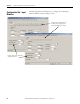
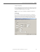
Scaling to Engineering Units
Channel data values in the output tag can be in engineering units such as kg, m,
or percent. To configure the relationship between engineering units and the
physical signal in volts or mA, set the Low and High Signal and the Low and
High Engineering values.
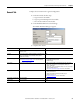
For example, if you have a temperature transmitter on channel 3 that produces
4 mA current at -180 °C (-292 °F) and 20 mA of current at 750 °C (1,382 °F),
and you want to use °C in your control program, then configure the values as in
the following table.
If you are using HART field devices, we recommend setting Engineering High
and Low to the field device's Upper Range Value and Lower Range Value so that
the field device uses the same engineering units as the 1756-IF8H module. If
online, these values are displayed on the HART Device Info tab.
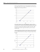
See the Scaling Example on page 99
for more information.
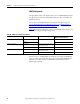
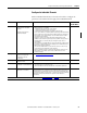
Scaling High and Low Signal
Set the High and Low Signal values for the module. The High Signal value must
be greater than the Low Signal value. See the following table for the bounds of
these signals.
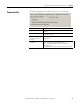
Scaling High Engineering
Set the High Engineering value for the module. The High Engineering value
must not equal the Low Engineering value. This is the value in engineering units
that corresponds with a signal value equal to the High signal.
Valid values are in the range of -10,000,000…100,000,000. The default value
is 100.00.
Scaling High Engineering appears dimmed in Hard Run mode.
Signal Engineering
High 20 750
Low 4 -180
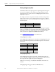
Range Low Limit High Limit
-10…10V -10.00 10.00
0…20 mA 0.00 20.00
4…20 mA 4.00 20.00
0…5V 0.00 5.00
0…10V 0.00 10.00