
Owner manual

Rockwell Automation Publication 1756-UM533C-EN-P - February 2011 97
Configure the Modules with RSLogix 5000 Software Chapter 7
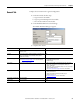
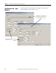
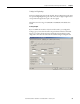
Configure the Individual Channels
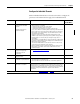
With an individual channel button selected, use this table to configure the
parameters in the Channel box that apply to the individual channels.
Parameter Action Notes Available in
Hard Run Mode?
Enable HART Check or uncheck for the
1756-IF8H and 1756-OF8H
modules.
Defaults checked for the
1756-IF16H module.
• Input range must be 0…20 mA or 4…20 mA.
• When a channel is not enabled:
– HART messages are not sent on this channel.
– HART pass-through messages are not sent.
– HART data for this channel is not updated in the input tag.
• If you select a HART PV or HART by Channel input tag on the General tab,
process data (PV, SV, TV, and FV) from the HART instrument is included in
the input tag. If you selected Analog only, the additional process data is
not included in the input tag.
• Regardless of the choice of input tag, HART communication can be
enabled for each channel to provide pass-through HART message access.
If Enable HART is not checked, this pass-through message access is
not available.
• We recommend you Enable HART for any channel that has a HART device
connected so that information can be displayed on the HART Device Info
tab and accessed by AssetCentre.
• You can check Enable HART on some channels and not on others if only
some channels have HART field devices attached.
• Because the HART modem is shared by all the channels, HART response
time is better if you enable only the needed HART channels on the
8-channel modules.
No
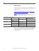
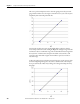
Scaling Enter scaling values for High
Signal, Low Signal, High
Engineering, and Low
Engineering.
See Scaling to Engineering Units on page 98 for more information. No
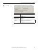
Input Range Choose a value from the
drop-down menu.
0…20 mA or 4…20 mA is required for HART. No
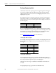
Sensor Offset Enter a value from
-9,999,999…99,999,999 (float).
• The default value is 0.00.
• The offset value is in engineering units.
• The Sensor Offset is added to the data value to determine signal level.
No
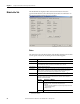
Digital Filter Select a filter time constant
value from 0…20100 ms.
This field is a first-order lag filter that smooths input transitions. It is called a
digital filter because it is calculated in the software by the module, not by a
hardware filter. The digital filter is applied to each channel individually, but
the module filter applies to all channels, so each channel can have a different
digital filter setting to accommodate the specific device attached to
that channel.
No
For descriptions of the other boxes, such as Real Time Sample (RTS), see Configure All Channels
on page 101.