
Owner manual

72 Rockwell Automation Publication 1756-UM533C-EN-P - February 2011
Chapter 5 1756-IF16H HART Analog Input Module
Wire-off Detection
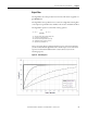
The 1756-IF16H module alerts you when a signal wire is disconnected from one
of its channels or the RTB is removed from the module if the channel is
configured for 4…20 mA range. When a wire-off condition occurs for this
module, two events occur:
• Input data for that channel changes to the scaled value corresponding to
the Underrange condition.
• A fault bit is set in the input tag (ChxxUnderrange and ChxxBrokenWire
tags are set to 1), which may indicate the presence of a wire-off condition.
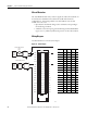
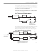
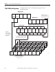
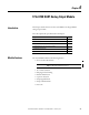
Wiring Diagram
Use this information to wire the current inputs.
Figure 12 - Current Inputs
+
-
+
-
+
--
+ -
2 Wire HART Device
4 Wire HART Device
IN0+
IN1+
IN2+
IN3+
RTN
IN4+
IN5+
IN6+
IN7+
IN8+
IN9+
IN10+
IN11+
RTN
IN12+
IN13+
IN14+
IN15+
IN0-
IN1-
IN2-
IN3-
RTN
IN4-
IN5-
IN6-
IN7-
IN8-
IN9-
IN10-
IN11-
RTN
IN12-
IN13-
IN14-
IN15-
2
4
6
8
10
12
14
16
18
20
22
24
26
28
30
32
34
36
1
3
5
7
9
11
13
15
17
19
21
23
25
27
29
31
33
35
24V DC
Power
Supply
24V DC
Power
Supply
4 Wire
XMTR
2 Wire
XMTR
+
45124
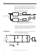
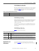
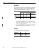
Channel Pin # Usage Usage Pin #
00 2 IN00+ IN00- 1
01 4 IN01+ IN01- 3
02 6 IN02+ IN02- 5
03 8 IN03+ IN03- 7
10 RTN RTN 9
04 12 IN04+ IN04- 11
05 14 IN05+ IN05- 13
06 16 IN06+ IN06- 15
07 18 IN07+ IN07- 17
08 20 IN08+ IN08- 19
09 22 IN09+ IN09- 21
10 24 IN10+ IN10- 23
11 26 IN11+ IN11- 25
28 RTN RTN 27
12 30 IN12+ IN12+ 29
13 32 IN13+ IN13+ 31
14 34 IN14+ IN14+ 33
15 36 IN15+ IN15+ 35