
Owner manual

60 Rockwell Automation Publication 1756-UM533C-EN-P - February 2011
Chapter 4 1756-IF8H HART Analog Input Module
Wiring Diagrams
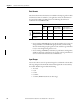
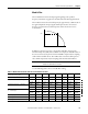
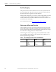
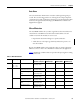
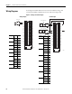
See the figures and tables that show how to wire the module for voltage and
current inputs. HART communication is active with current inputs only.
Figure 5 - Voltage and Current Inputs
RTN
IN4+
IN4-
IN5+
IN5-
RTN
IN6+
IN6-
IN7+
IN7-
IN0+
IN0-
IN1+
IN1-
IN2+
IN2-
IN3+
IN3-
I RTN-0
NC
I RTN-1
NC
I RTN-2
NC
I RTN-3
NC
RTN
I RTN-4
NC
I RTN-5
NC
RTN
I RTN-6
NC
I RTN-7
NC
2
4
6
8
10
12
14
16
18
20
22
24
26
28
30
32
34
36
1
3
5
7
9
11
13
15
17
19
21
23
25
27
29
31
33
35
+V
- V
Voltage Input
44222
Channel Usage Pin #
0IN0+2
IN0- 4
1IN1+6
IN1- 8
2IN2+12
IN2- 14
3IN3+16
IN3- 18
4IN4+20
IN4- 22
5IN5+24
IN5- 26
6IN6+30
IN6- 32
7IN7+34
IN7- 36
Voltage Inputs
Current Inputs
RTN
IN4+
IN4-
IN5+
IN5-
RTN
IN6+
IN6-
IN7+
IN7-
IN0+
IN0-
IN1+
IN1-
IN2+
IN2-
IN3+
IN3-
I RTN-0
NC
I RTN-1
NC
I RTN-2
NC
I RTN-3
NC
RTN
I RTN-4
NC
I RTN-5
NC
RTN
I RTN-6
NC
I RTN-7
NC
2
4
6
8
10
12
14
16
18
20
22
24
26
28
30
32
34
36
1
3
5
7
9
11
13
15
17
19
21
23
25
27
29
31
33
35
XMTR
+
-
+
-
+
+
--
+ -
2-wire Current Input
2-wire
4-wire Current Input
4-wire
MTR
24V DC
Power
Supply
24V DC
Power
Supply
44223
Channel Usage Pin #
0 iRTN0 1
IN0+ 2
IN0- 4
1 iRTN1 5
IN1+ 6
IN1- 8
2iRTN211
IN2+ 12
IN2- 14
3iRTN315
IN3+ 16
IN3- 18
4iRTN419
IN4+ 20
IN4- 22
5iRTN523
IN5+ 24
IN5- 26
6iRTN629
IN6+ 30
IN6- 32
7iRTN733
IN7+ 34
IN7- 36