
Owner manual

Rockwell Automation Publication 1756-UM533C-EN-P - February 2011 175
Tag Definitions Appendix A
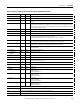
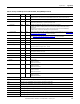
Analog and HART PV
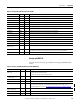
This table describes the input tags available in the Analog and HART PV data
format.
Ch02Status SINT Binary Indicates various alarms on the analog signal. Also sets Ch02Fault.
Ch03Status SINT Binary Indicates various alarms on the analog signal. Also sets Ch03Fault.
Ch04Status SINT Binary Indicates various alarms on the analog signal. Also sets Ch04Fault.
Ch05Status SINT Binary Indicates various alarms on the analog signal. Also sets Ch05Fault.
Ch06Status SINT Binary Indicates various alarms on the analog signal. Also sets Ch06Fault.
Ch07Status SINT Binary Indicates various alarms on the analog signal. Also sets Ch07Fault.
Ch08Status SINT Binary Indicates various alarms on the analog signal. Also sets Ch08Fault.
Ch09Status SINT Binary Indicates various alarms on the analog signal. Also sets Ch09Fault.
Ch10Status SINT Binary Indicates various alarms on the analog signal. Also sets Ch10Fault.
Ch11Status SINT Binary Indicates various alarms on the analog signal. Also sets Ch11Fault.
Ch12Status SINT Binary Indicates various alarms on the analog signal. Also sets Ch12Fault.
Ch13Status SINT Binary Indicates various alarms on the analog signal. Also sets Ch13Fault.
Ch14Status SINT Binary Indicates various alarms on the analog signal. Also sets Ch14Fault.
Ch15Status SINT Binary Indicates various alarms on the analog signal. Also sets Ch15Fault.
ChxxData
(Ch00…Ch15)
REAL Float Value of analog signal on Channel xx after conversion to engineering units.
CSTTimestamp DINT[2] Hex Timestamp taken at the time the input data was sampled in terms of Coordinated System Time, which
is a 64-bit value in microseconds coordinated across the modules in the 1756 backplane.
RollingTimestamp INT Decimal Timestamp taken at the time the input data was sampled in millisecond resolution.
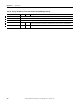
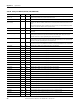
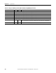
Table 63 - Analog Only (AB:1756_IF16H_Analog:I:0)
Member Name Type Style Description
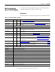
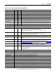
Table 64 - Analog and HART PV (AB:1756_IF16H_HARTPV:I:0)
Member Name Type Style Description
ChannelFaults
(bit0…15)
INT Binary Indicates a problem with analog data on Channel x or broken communication between the Logix
controller and the 1756-IF16H module.
Example: Set if analog signal is larger than 20 mA.
ChxxFault
(Ch0…Ch15)
BOOL Decimal ChannelFaults.0…ChannelFaults.15
Module Status SINT Binary
Calibrating BOOL ModuleStatus.0, Calibration in progress
UpdatedStatusReady BOOL ModuleStatus.1, Module has collected updated Additional Device Status from HART command 48.
This status can be retrieved by using the Read Additional Status service, 16#4C. For more
information about this service, see Read Additional Status (Service Code = 16#4C) on page 125
.
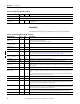
ModuleFaults
(bits0…5 not used)
SINT Binary
CalFault BOOL Decimal ModuleFaults.6, 1756-IF16H Module Calibration Failed.
AnalogGroupFault BOOL Decimal ModuleFaults.7, Indicates a fault has occurred on any channel (any of ChannelFaults).