
Owner manual

168 Rockwell Automation Publication 1756-UM533C-EN-P - February 2011
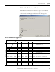
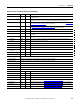
Appendix A Tag Definitions
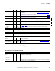
Ch0HAlarm BOOL Ch0Status.2
Ch0Data > Ch0HAlarmLimit
If Ch0Config.ProcessAlarmLatch is set, this alarm remains set until it is unlatched
Ch0LAlarm BOOL Ch0Status.3
Ch0Data < Ch0LAlarmLimit
If Ch0Config.ProcessAlarmLatch is set, this alarm remains set until it is unlatched.
Ch0RateAlarm BOOL Ch0Status.4
Ch0Data changing faster than Ch0RateAlarmLimit.
Both positive and negative changes can cause this alarm.
If Ch0Config.RateAlarmLatch is set, this alarm remains set until it is unlatched.
Ch0Overrange BOOL Ch0Status.5
Analog signal is greater than or equal to the maximum detectable signal. Because the signal cannot
be measured, it may be significantly above the maximum value.
Ch0Underrange BOOL Ch0Status.6
Analog signal is less than or equal to the minimum detectable signal. Because the signal cannot be
measured, it may be significantly below the minimum value.
Ch0CalFault BOOL Ch0Status.7
Set if an error occurs during calibration for Channel x, causing a bad calibration. Also sets CalFault.
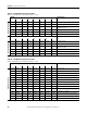
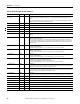
Ch1Status SINT Binary Indicates various alarms on the analog signal. Also sets Ch1Fault.
Ch2Status SINT Binary Indicates various alarms on the analog signal. Also sets Ch2Fault.
Ch3Status SINT Binary Indicates various alarms on the analog signal. Also sets Ch3Fault.
Ch4Status SINT Binary Indicates various alarms on the analog signal. Also sets Ch4Fault.
Ch5Status SINT Binary Indicates various alarms on the analog signal. Also sets Ch5Fault.
Ch6Status SINT Binary Indicates various alarms on the analog signal. Also sets Ch6Fault.
Ch7Status SINT Binary Indicates various alarms on the analog signal. Also sets Ch7Fault.
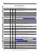
Ch0Data REAL Float Value of analog signal on Channel 0 after conversion to engineering units.
Ch1Data REAL Float Value of analog signal on Channel 1 after conversion to engineering units.
Ch2Data REAL Float Value of analog signal on Channel 2 after conversion to engineering units.
Ch3Data REAL Float Value of analog signal on Channel 3 after conversion to engineering units.
Ch4Data REAL Float Value of analog signal on Channel 4 after conversion to engineering units.
Ch5Data REAL Float Value of analog signal on Channel 5 after conversion to engineering units.
Ch6Data REAL Float Value of analog signal on Channel 6 after conversion to engineering units.
Ch7Data REAL Float Value of analog signal on Channel 7 after conversion to engineering units.
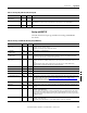
CSTTimestamp DINT[2] Hex Timestamp taken at the time the input data was sampled in terms of coordinated system time,
which is a 64-bit value in microseconds coordinated across the modules in the 1756 backplane.
RollingTimestamp INT Decimal Timestamp taken at the time the input data was sampled in millisecond resolution.
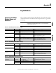
HART AB:1756_IF8H_HARTData:I:1, Contains HART field device health and dynamic process variables.
Ch0DeviceStatus AB:1756_IF8H_HARTStatus_Struct:I:1, Channel 0 HART Device status info.
Init BOOL Searching for or Initializing HART device.
If this is 0 and Fail is 1, then HART is not enabled on this channel.
If both are 1, then 1756-IF8H is sending out HART messages attempting to establish communication
with a HART device.
Fail BOOL HART communication failure or device not found or HART not enabled.
If this bit is 1, none of the other data in the HART part of the input tag are valid.
(HART.PVStatus will be set to 0 to also indicate this).
MsgReady BOOL Pass-through message reply is ready for query service.
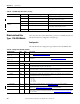
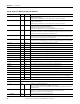
Table 60 - Analog and HART PV (AB:1756_IF8H_HARTPV:I:1)
Member Name Type Style Description