
Owner manual

Rockwell Automation Publication 1756-UM533C-EN-P - February 2011 167
Tag Definitions Appendix A
Analog and HART PV
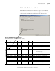
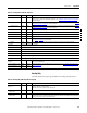
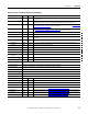
This table describes the input tags available in the Analog and HART PV
data format.
ChxData
(Ch0…Ch7)
REAL Float Value of analog signal on Channel x after conversion to engineering units.
CSTTimestamp DINT[2] Hex Timestamp taken at the time the input data was sampled in terms of coordinated system time, which
is a 64-bit value in microseconds coordinated across the modules in the 1756 backplane.
RollingTimestamp INT Decimal Timestamp taken at the time the input data was sampled in millisecond resolution.
Table 59 - Analog Only (AB:1756_IF8H_Analog:I:0)
Member Name Type Style Description
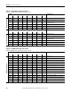
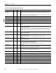
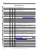
Table 60 - Analog and HART PV (AB:1756_IF8H_HARTPV:I:1)
Member Name Type Style Description
ChannelFaults
(bit0…15)
INT Binary Indicates a problem with analog data on Channel x or broken communication between the Logix
controller and the 1756-IF8H module.
Example: Set if analog signal is larger than 20 mA.
ChxFault
(Ch0…Ch7)
BOOL Decimal ChannelFaults.0…ChannelFaults.7
ChxBrokenWire
(Ch0…Ch7)
BOOL Decimal ChannelFaults.8…ChannelFaults.15
Indicates that current is not flowing through the module as expected. This might be caused by
broken wiring, RTB removal, or a powered-off field device.
HARTFaults
(Ch0…Ch7)
SINT Binary Indicates a problem with HART data from the field device on Channel x.
Examples are HART not enabled, HART device not connected, HART communication failure due to
noise.
The following field device status conditions also cause this to be set: Device Malfunction,
PV Out of Limits, Loop Current Saturated, and Loop Current Fixed.
ChxHARTFault BOOL Decimal HARTFaults.0…HARTFaults.7
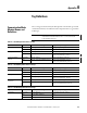
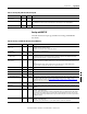
ModuleFaults SINT Binary
CalFault BOOL Decimal ModuleFaults.1, 1756-IF8H Module Calibration Failed.
Calibrating BOOL Decimal ModuleFaults.2, Calibration in progress.
UpdatedStatusReady BOOL Decimal ModuleFaults.3, Module has collected updated Additional Device Status from HART command 48.
This status can be retrieved by using the Read Additional Status service, 16#4C. For more
information about this service, see Read Additional Status (Service Code = 16#4C) on page 125
.
Updated Cmd 48 status data available.
AnalogGroupFault BOOL Decimal ModuleFaults.7, Indicates a fault has occurred on any channel (any of ChannelFaults).
Ch0Status SINT Binary Indicates various alarms on the analog signal. Also sets Ch0Fault for Overrange, Underrange, and
CalFault.
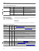
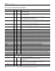
Ch0HHAlarm BOOL Ch0Status.0
Ch0Data > Ch0HHAlarmLimit.
If process alarms are configured to latch by setting Ch0Config.ProcessAlarmLatch this bit remains
set even after the condition returns to normal, until reset via explicit CIP message. This message
can be sent from the RSLogix 5000 Module Properties Alarm dialog box or from the Logix controller
via MSG instruction.
Ch0LLAlarm BOOL ChxStatus.1
Ch0Data < Ch0LLAlarmLimit
If Ch0Config.ProcessAlarmLatch is set, this alarm remains set until it is unlatched.