
Owner manual

164 Rockwell Automation Publication 1756-UM533C-EN-P - February 2011
Appendix A Tag Definitions
Module-defined Data
Types, 1756-IF8H Module
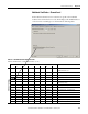
These tables describe module-defined data types for the 1756-IF8H module and
include information for configuration and input tags.
Configuration
This table describes the configuration tags available in the 1756-IF8H module.
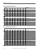
Analog and HART PV Configuration AB:1756_OF8H:C:0 AB:1756_OF8H_ChConfig_Struct:C:0
Input AB:1756_OF8H_HARTPV:I:1 AB:1756_OF8H_HARTData:I:1
AB:1756_OF8H_HARTStatus_Struct:I:1
Output AB:1756_OF8H:O:0 None
Analog and HART by
Channel
Configuration AB:1756_OF8H:C:0 AB:1756_OF8H_ChConfig_Struct:C:0
Input
AB:1756_OF8H_AnalogHARTbyChannel:I:0
AB:1756_OF8H_HARTDataAll_Struct:I:0
AB:1756_OF8H_HARTStatusAll_Struct:I:0
Output AB:1756_OF8H:O:0 None
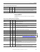
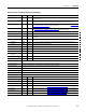
Table 57 - 1756-OF8H Input Data Choice and Tags
Input Data Choice Tag Main Module Defined Type Subtype Used by Main Type
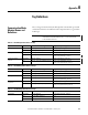
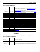
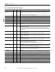
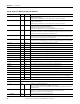
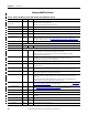
Table 58 - Configuration (AB:1756_IF8H:C:0)
Member Name Type Style Description
ModuleFilter
(bits 0…7)
SINT Decimal See the Module Filter Values table on page 103.
RealTimeSample
(bits 0…15)
INT Decimal Milliseconds between reading signal values. See Real Time Sample (RTS) on page 41 for more
information.
Ch0Config AB:1756_IF8H_ChConfig_Struct:C:0
Config SINT Binary
RateAlarmLatch BOOL Decimal Ch0Config.Config.4, After a Rate Alarm is detected, keep I.ChxRateAlarm set even after Rate returns
to normal, until unlatched by CIP Service Message.
ProcessAlarmLatch BOOL Decimal Ch0Config.Config.5, After a Process Alarm such as LL is detected, keep I.ChxLLAlarm set even after
measurement returns to normal, until unlatched by CIP Service Message.
AlarmDisable BOOL Decimal Ch0Config.Config.6, Do not report Process or Rate Alarms.
HARTEn BOOL Decimal Ch0Config.Config.7, Enable HART communication. Must be 1 for valid HART data in Input Tag and
Asset Management access to HART Field Device.
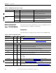
RangeType SINT Decimal 0 = -10…+10 V.
1 = 0…5 V.
2 = 0…10 V.
3 = 0…20 mA.
4 = 4 …20 mA.
DigitalFilter INT Decimal Time Constant of low pass filter in ms. See Digital Filter on page 71
for more information.
RateAlarmLimit REAL Float Maximum Ramp Rate value to trigger a Rate Alarm when the Input Signal rate of change exceeds the
setpoint. See Scaling to Engineering Units on page 98
for more information.
LowSignal REAL Float Lower current value for scaling to engineering units. Default is 4 mA. Must be less than HighSignal
and more than or equal to the minimum Input Range. See Scaling to Engineering Units on page 98 for
more information.