
Owner manual

Rockwell Automation Publication 1756-UM533C-EN-P - February 2011 155
Chapter
11
Module Troubleshooting
Introduction
This chapter describes how to interpret status indicators and troubleshoot
the modules.
These topics are discussed in this chapter.
Use Module Indicators
The analog I/O modules have indicators that provide indication of module
status. ControlLogix modules use status indicators as shown in the table.
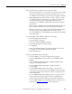
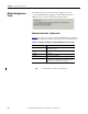
The illustration below shows the status indicators used with ControlLogix analog
input HART modules.
The following tables provide a description of the colors that display in the
status indicators.
Topic Page
Use Module Indicators 155
General Troubleshooting Tips 156
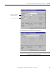
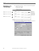
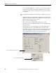
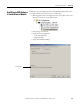
Use RSLogix 5000 Software to Troubleshoot a Module 159
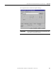
Module Configuration Errors 160
ANALOG INPUT
CAL
OK
20962-M
Table 49 - ControlLogix Module Status Indicators
Indicator Display Means Recommended Action
OK Steady Green The inputs are being multicast None
OK Flashing Green The module has passed internal diagnostics, but is not currently performing connected
communication
None
OK Flashing Red Previously established communication has timed out Check controller
OK Steady Red It is likely the module should be replaced See the blink codes
(1)
CAL Flashing Green The module is in Calibration mode None
(1) Under fault conditions the module communicates a particular error via the status indicator blink codes. Table 50
provides a description of the fault
conditions and blink codes.