
Owner manual


14 Rockwell Automation Publication 1756-UM533C-EN-P - February 2011
Chapter 1 ControlLogix HART Analog I/O Modules
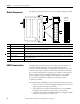
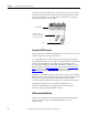
Module Components
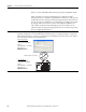
This figure shows the physical features of the ControlLogix analog I/O modules.
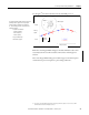
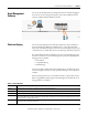
HART Communication
The HART field communication protocol is widely accepted in industry as a
standard for digitally enhanced 4…20 mA communication with smart
(microprocessor-based) field devices. A digital signal is superimposed onto the
4…20 mA current loop to provide two means of communication from the device.
The 4…20 mA analog channel lets a single process variable be communicated at
the fastest possible rate while the digital channel provides access to multiple
process variables, data quality, and device status information. The HART
protocol lets these simultaneous communication channels be used in a
complementary fashion.
The modules support the HART protocol and perform these distinct operations:
• Convert to or from 4…20 mA analog signals and digital numeric values in
engineering units used in the Logix controller.
• Collect dynamic process data automatically from the connected HART
field device, such as temperature, pressure, flow, or valve position.
• Configure and troubleshoot the HART Field Device by using FactoryTalk
AssetCentre service from your control room.
# Physical Feature Description
1 Backplane connector The backplane connector interface for the ControlLogix system connects the module to the ControlBus backplane.
2 Connector pins Input/output, power, and grounding connections are made to the module through these pins with the use of a
removable terminal block (RTB) or interface module (IFM).
3 Locking tab The locking tab anchors the RTB or IFM cable on the module, maintaining wiring connections.
4 Slots for keying Mechanically keys the RTB to prevent inadvertently making the wrong wire connections to the module.
5 Status indicators Indicators display the status of communication, module health, and input and output devices. Use these indicators
to help in troubleshooting.
6 Top and bottom guides Guides provide assistance in seating the RTB or IFM cable onto the module.
Removable
Terminal
Block (RTB)
45118
1
2
3
4
5
6