
Owner manual

Rockwell Automation Publication 1756-UM533C-EN-P - February 2011 109
Configure the Modules with RSLogix 5000 Software Chapter 7
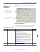
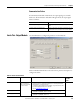
Communication Failure
If communication fails while in Run mode, the output signal goes to its Fault
Mode state. If communication fails while in Program mode, the output signal
behaves as follows.
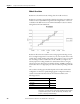
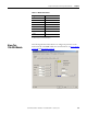
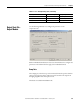
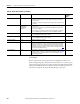
Limits Tab - Output Module
Use this information to configure the parameters on the Limits tab.
With an individual channel button selected, use these parameter descriptions to
configure the alarms.
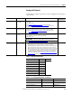
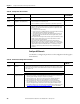
Select To
Leave outputs in Program mode state Leave output signal at the configured Program mode
value
Change output to Fault mode state Change output signal at configured Fault mode value if a
communication fails (connection from controller breaks)
Table 28 - Alarm Tab Parameters
Parameter Action Notes Available in
Hard Run
Mode?
Limits Enter values or drag
the corresponding
flags on the slider bar
to set the values.
• The maximum and minimum values for these alarms are set by the High
Engineering and Low Engineering parameters on the Configuration tab.
• Clamp limits are in engineering units.
• To change the trigger points by whole numbers only, hold down the shift
key while dragging the flag on the slider bar.
• See the Limit Example on page 110
.
No
High Clamp (HI) • The highest value an output channel can reach in the control process.
• -9,999,999…99,999,999, default is 100.00.
Low Clamp (LO) • The lowest value an output channel can reach in the control process.
• -9,999,999…99,999,999, default is 0.