
Manual

Publication 1756-UM524B-EN-P - December 2008
Chapter
2
Install the 1756-CLX/C Module
What This Chapter Contains
This chapter describes how to install the 1756-CLX/C module into a ControlLogix
chassis.
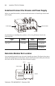
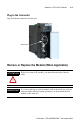
Identify Module Components
Refer to Module Features on page 1-2 for an illustration that will help you identify the
module components.
About the Jumpers
For information about this topic See page
Identify Module Components 2-1
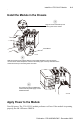
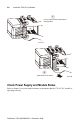
Install and Connect the Chassis and Power Supply 2-2
Determine Module Slot Location 2-2
Install the Module in the Chassis 2-3
Apply Power to the Module 2-3
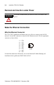
Removal and Insertion under Power 2-4
Make the Ethernet Connection 2-4
Remove or Replace the Module (When Applicable) 2-5
Check Power Supply and Module Status 2-6
ATTENTION
All jumpers on the 1756-CLX/C module are factory-set and should not
be changed. If you change a jumper by mistake, refer to Appendix B of
this manual to reset it to the proper position.