NeXUS Module 1756-CLX/C User Manual
Important User Information Because of the variety of uses for the products described in this publication, those responsible for the application and use of these products must satisfy themselves that all necessary steps have been taken to assure that each application and use meets all performance and safety requirements, including any applicable laws, regulations, codes and standards.
ATTENTION Environment and Enclosure This equipment is intended for use in a Pollution Degree 2 industrial environment, in overvoltage Category II applications (as defined in IEC publication 60664-1), at altitudes up to 2000 meters without derating. This equipment is supplied as "open type" equipment.
Technical Product Assistance If you need to contact Rockwell Automation for technical assistance, please review the troubleshooting information first. If the problem persists, contact a Rockwell Automation representative at the following location: Rockwell Automation Japan Co., Ltd.
Preface What This Preface Contains This preface describes how to use this manual. The following table describes what this preface contains and where to find it.
P-2 Preface What This Manual Contains This user manual contains the following sections: Chapter 1 - About the 1756-CLX/C Module Description of the 1756-CLX/C module Chapter 2 - Install the 1756-CLX/C Module Description of how to install the 1756-CLX/C module and connect the Ethernet cable Chapter 3 - About the NeXUS Network Overview of the NeXUS network and functions supported by the 1756-CLX/C module Chapter 4 - Configure the 1756-CLX/C Module Description of how to configure the 1756-CLX/C module with
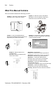
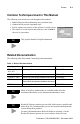
Preface P-3 Common Techniques Used in This Manual The following conventions are used throughout this manual: • • • • Bulleted lists provide information, not procedural steps Numbered lists provide sequential steps Screen captures are pictures of the software’s actual screens The names of screen buttons and fields are often in bold in the text of a procedure TIP This symbol identifies helpful information.
P-4 Preface Notes: Publication 1756-UM524B-EN-P - December 2008
Table of Contents Important User Information . . . . . . . . . . . . . . . . . . . . . . . . . . . . . . . . . . . . . . . Rockwell Automation Support . . . . . . . . . . . . . . . . . . . . . . . . . . . . . . . . . . . . . Product Support. . . . . . . . . . . . . . . . . . . . . . . . . . . . . . . . . . . . . . . . . . . . . Technical Product Assistance . . . . . . . . . . . . . . . . . . . . . . . . . . . . . . . . . . 1-2 1-3 1-3 1-4 Preface What This Preface Contains . . . . . . . . . . . . . . . .
TOC-ii Table of Contents Make the Ethernet Connection . . . . . . . . . . . . . . . . . . . . . . . . . . . . . . . . . . . . . Wire the Ethernet Connector. . . . . . . . . . . . . . . . . . . . . . . . . . . . . . . . . . . Plug in the Connector . . . . . . . . . . . . . . . . . . . . . . . . . . . . . . . . . . . . . . . . Remove or Replace the Module (When Applicable) . . . . . . . . . . . . . . . . . . . . Check Power Supply and Module Status . . . . . . . . . . . . . . . . . . . . . . . . . . . . .
Table of Contents TOC-iii Appendix A Specifications Appendix B Factory-set Jumpers Appendix C 1756-CLX/C Web Interface User Screens . . . . . . . . . . . . . . . . . . . . . . . . . . . . . . . . . . . . . . . . . . . . . . . . . . . C-1 Appendix D 1756-CLX/C Module Backplane Communication Tag List About the Nexus Communication Flags (NX20 – NX91) . . . . . . . . . . . . . . . Boot /Reboot 1756-CLX/C Module Procedure. . . . . . . . . . . . . . . . . . . . 1756-CLX/C Module Configuration Check Procedure .
TOC-iv Table of Contents Publication 1756-UM524B-EN-P - December 2008
Chapter 1 About the 1756-CLX/C Module What This Chapter Contains This chapter provides an overview of the 1756-CLX/C module, its primary features, what it does, and how to use it. You will need to understand the concepts discussed in this chapter in order to configure your module and use it in a control system. The following table lists where to find specific information in this chapter..
1-2 About the 1756-CLX/C Module The module mounts into a ControlLogix chassis. It communicates with Logix controllers across the ControlLogix chassis backplane. The module connects to the NeXUS network via an Ethernet cable.
About the 1756-CLX/C Module 1-3 Alpha-numeric display Status indicators Reset Switch (schematic view; actual switch is inside module) Ethernet port with status indicators Some Points to Remember Remember the following points about the 1756-CLX/C module: • the module is not supported by RSLinx or RSNetworx software • the module does not support bridging between NeXUS and ControlNet, DeviceNet, EtherNet/IP, or any other network • the module does not support bridging between NeXUS sub-nets (i.e.
1-4 About the 1756-CLX/C Module About the Battery The 1756-CLX/C module uses a rechargeable lithium vanadium pentoxide battery, which, when fully charged, provides backup power for the SRAM memory for approximately 21 days. The module must be powered for approximately 20 hours before the battery becomes fully charged. The battery is not accessible, and should last for the life of the module. ATTENTION The lithium battery is not user-replaceable. Do not attempt to access or replace it.
About the 1756-CLX/C Module 1-5 Preventing Electrostatic Discharge This module is sensitive to electrostatic discharge. ATTENTION Preventing Electrostatic Discharge This equipment is sensitive to electrostatic discharge, which can cause internal damage and affect normal operation. Follow these guidelines when you handle this equipment: • • • • • • Touch a grounded object to discharge potential static. Wear an approved grounding wrist strap. Do not touch connectors or pins on component boards.
1-6 About the 1756-CLX/C Module 1756-CLX/C Module Architecture The figure below shows how the various components of a system using the 1756-CLX/C module interact. Backplane Backplane communication Application (ladder) 1756-CLX/C API Backplane communication 1756-CLX/C module 1756-CLX/C message handling Tags (data) Logix5000 Controller Windows NT 4.0 (UDP/IP) 1756-CLX/C Dlink SMG/BS Ethernet port Configuration Overview The figure below shows an overview of the configuration process.
About the 1756-CLX/C Module 1-7 Process Overview The figure below shows the flow of data to and from the 1756-CLX/C module. Control Logix ControlLogix Application ladder Application (Ladder) Tags TAGs Syst em Status System status NX20 ` NX51 (NX20 - NX51) System System config. Configuration (NX00 NX00- NX07) ` 07 Recvparameters -Parametersand Recv.
1-8 About the 1756-CLX/C Module Notes: Publication 1756-UM524B-EN-P - December 2008
Chapter 2 Install the 1756-CLX/C Module What This Chapter Contains This chapter describes how to install the 1756-CLX/C module into a ControlLogix chassis.
2-2 Install the 1756-CLX/C Module Install and Connect the Chassis and Power Supply Before you install the module, you must install and connect a ControlLogix chassis and power supply. Power Supply 1756-A4 Chassis 20805-M For information on installing these products, refer to the publications listed in the following table. Chassis Type Chassis Installation Power Supply Power Supply Installation Series B: 1756-A4, -A7, -A10, -A13, -A17 Pub. No. 1756-IN08C 1756-PA72/B Pub. No.
Install the 1756-CLX/C Module 2-3 Install the Module in the Chassis 1 Align the circuit board with top and bottom guides in the chassis. Circuit Board 31275-M 2 Slide the module into the chassis. Make sure the module backplane connector properly connects to the chassis backplane. Check that the holding clips on the top and bottom of the module are securely in the locking holes of the rack. 3 The module is properly installed when it is flush with the power supply or other installed modules.
2-4 Install the 1756-CLX/C Module Removal and Insertion under Power WARNING We do not recommend that you install or remove the module under power. Make the Ethernet Connection Wire the Ethernet Connector The 1756-CLX/C module has an Ethernet port you will use to connect to the NeXUS network. Use an RJ45 connector to connect to the Ethernet network.
Install the 1756-CLX/C Module 2-5 Plug in the Connector Plug the Ethernet connector into the port. Ethernet port Remove or Replace the Module (When Applicable) ATTENTION IMPORTANT Before you remove the module, you must disconnect the Ethernet cable. If you are replacing an existing module with an identical one, and you want to resume identical system operation, you must install the new module in the same slot.
2-6 Install the 1756-CLX/C Module 1 Push on upper and lower module tabs to disengage them. 31277-M 2 Slide module out of chassis. 31278-M Check Power Supply and Module Status Refer to chapter 5 to use the status indicators to determine that the 1756-CLX/C module is operating correctly.
Chapter 3 About the NeXUS Network What This Chapter Contains This chapter provides a brief overview of the NeXUS network. The following table describes what this chapter contains and where to find it.
3-2 About the NeXUS Network OSI Layer NeXUS Network Protocol Comments Layer 7 - Application NEXUS or ADP Layer 6 - Presentation Not implemented Layer 5 - Session Not implemented Layer 4 - Transport UDP and TCP Layer 3 - Network IP Layer 2 - Data Link IEEE/802.3 - Ethernet Layer 1 - Physical IEEE/802.3 - Ethernet Physical Medium IEEE/802.3 - Ethernet See the latest copy of the following ADP specification, available at http://www.mstc.or.jp/jop/misc/spec-e .
About the NeXUS Network 3-3 Network Organization Looking from the top down, a NeXUS network is viewed as a system of islands called domains, interconnected via a wide area network. Each domain is uniquely identified by a domain number (DMN), which ranges from 1 to 64. The domain number must be provided in all ADP PDU headers. DMN 0 is reserved for the domain considered within the scope of the ADP specification. A domain is divided into data fields.
3-4 About the NeXUS Network Supported ADP Message Types The 1756-CLX/C module supports the following communication features referenced in the ADP specification: Communication Class Feature Clause (in ADP Requirements for Conformance specification) Transmission Reception Multicast communication Base-1 4.1 Supported Supported Alive signal Base-1 4.2 Supported Not supported Communication Clause (in ADP Feature specification) Test support Maximum message length 4.
About the NeXUS Network Class B 0 1 Class D 1 1 Network ID 16 8 31 24 host ID 16 8 24 Network ID 0 16 1 31 24 host ID Network ID 0 1 1 0 0 1 Class C 1 1 16 8 0 1 Class A 0 3-5 Multicast ID 0 24 31 host ID 31 host ID Each node on the same physical network must have an IP address of the same class and must have the same nework or multicast ID. Each node on the same network must have a different host ID, giving it a unique IP address.
3-6 About the NeXUS Network Gateways A gateway connects individual physical networks into a system of networks. When a node needs to communicate with a node on another network, a gateway transfers the data between the two networks. The following figure shows gateway G connecting Network 1 with Network 2. A 128.1.0.1 Network 1 128.1.0.2 G 128.2.0.3 C B 128.2.0.1 128.2.0.2 Network 2 When host B with IP address 128.2.0.
About the NeXUS Network 3-7 Subnet Mask Subnet addressing is an extension of the IP address scheme that allows a site to use a single net ID for multiple physical networks. Routing outside of the site continues by dividing the IP address into a net ID and a host ID via the class. Inside a site, the subnet mask is used to redivide the IP address into a custom net ID portion and host ID portion. Take Network 2 (a Class B network) in the previous example and add another physical network.
3-8 About the NeXUS Network For More Information For more information about Ethernet, refer to the following publications: Publication data ISBN Internetworking with TCP/IP Vol. 1, 2nd ed. by Douglas E. Comer ISBN 0-13-216987-8 The Ethernet Management Guide – Keeping The Link ISBN 0-07-046320-4 An Introduction to TCP/IP ISBN 3-540-96651-X Computer Networks by Andrew S.
Chapter 4 Configure the 1756-CLX/C Module What This Chapter Contains This chapter describes why you must configure your 1756-CLX/C module and how to configure it for use in the ControlLogix system. For information about this topic See page: Configure Your 1756-CLX/C Module 4-1 Create a New Module 4-2 View and Change Module Tags 4-5 Configure the Module IP Address 4-6 Configure Your 1756-CLX/C Module You must configure your module upon installation.
4-2 Configure the 1756-CLX/C Module Overview of the Configuration Process When you use the RSLogix 5000 software to configure a 1756-CLX/C module, you must perform the following steps: 1. Create a new module. 2. Accept the default configuration or change it to specific configuration for the module. 3. Edit configuration for a module when changes are needed. 4. Configure the module’s IP address. Create a New Module After you have started RSLogix 5000 and created a controller, you must create a new module.
Configure the 1756-CLX/C Module 4-3 When you are offline, you must select a new module. 1. 2. 3. Select I/O Configuration. Click on the right mouse button to display the menu. Select New Module A screen appears with a list of possible new modules for your application. Select a module from the list. Click OK. The new module creation wizard appears.
4-4 Configure the 1756-CLX/C Module After you name the page, this screen appears Inhibit the connection to the module here If you want a Major Fault on the Controller to occur if there is connection failure with the I/O module, click here Adjust the Requested Packet Interval here. The default RPI is 5ms. This Fault box is empty when you are offline.
Configure the 1756-CLX/C Module 4-5 View and Change Module Tags When you create a module, a set of tags are created by the ControlLogix system that can be viewed in the Tag Editor of RSLogix 5000. Each configurable feature on your module has a distinct tag that can be used in the processor’s ladder logic. You can access a module’s tags through RSLogix 5000 as shown below. 1. 2. 3. Select Controller Tags. Click on the right mouse button to display the menu. Select Monitor Tags.
4-6 Configure the 1756-CLX/C Module Configure the Module IP Address Before you can use your 1756-CLX/C module, you must configure its IP address, gateway, and subnet mask by specifying parameters NX00 through NX02 on the Logix5000 controller. Refer to Appendices D and E of this manual for definitions of these parameters.
Chapter 5 Status Indicators and Troubleshooting What This Chapter Contains This chapter shows you the status indicators on the 1756-CLX/C module, and provides basic troubleshooting procedures.
5-2 Status Indicators and Troubleshooting Use the LED Status Indicators The 1756-CLX/C module has the following LED status indicators. Use these indicators to troubleshoot module status.: Table 5.A LED Status Indicators This LED When Means So you should BAT (RED) ON The battery is low. Replace the module. The battery is charging. The BAT Wait for the battery to finish LED turns OFF within a few charging. minutes after power is applied. OFF USR (GREEN) OK (STATUS) The Battery is charged.
Status Indicators and Troubleshooting 5-3 Use the Communications Port Status Indicators The 1756-CLX/C module has the following communications port status indicators. Use these indicators to troubleshoot module communication: Table 5.B Communication Port Status Indicators This LED When operating like this, means So you should 10/100 (GREEN) (Top LED) • This LED will be ON if 100BASE-TX Do nothing. The module is operating link is detected and OFF if a correctly. 10BASE-T link is detected.
5-4 Status Indicators and Troubleshooting Table 5.D Firmware error codes Error type Error contents Alphanumeric display NX46_ System error NX60_ NX63_ System status error code level NX64_ Status code NX61_ VX62_ Event Send Receive log error code error code source User action ConfiguConfiguration ration Error Error ERR ON Error_ Code N/A N/A N/A NX SAM See Table 5.
Status Indicators and Troubleshooting 5-5 Table 5.E Module error codes No.
5-6 Status Indicators and Troubleshooting Table 5.F Send/receive error codes No.
Appendix A Specifications Module Location 1756 ControlLogix chassis Maximum Backplane Current 1A @ 5V dc Maximum Power Dissipation 5W Communication Ports Ethernet 10/100T IEEE 802.
A-2 Specifications Notes: Publication 1756-UM524B-EN-P - December 2008
Appendix B Factory-set Jumpers Jumpers on the 1756-CLX/C module are factory-set. If you change the jumper settings by mistake, follow this procedure to reset them. ATTENTION Do not change the jumper positions. If you change a jumper position by mistake, you must re-set it to the position shown below.
B-2 Factory-set Jumpers 32-bit (shown) 16-bit (shown) 1756-CLX/C CONFIGURATION JUMPER SETTINGS Front of module Publication 1756-UM524B-EN-P - December 2008
Appendix C 1756-CLX/C Web Interface The 1756-CLX/C module’s web page offers extensive internal and network diagnostics. To view the web pages, enter the module’s IP address into your web browser. You can access the following web pages. For information about this topic: User Screens See page: C-1 User Screens Figure C.
C-2 1756-CLX/C Web Interface Figure C.
1756-CLX/C Web Interface C-3 Figure C.3 Multicast group statistics screen TIP You can also access this screen by typing nxstat -m in a DOS window.
C-4 1756-CLX/C Web Interface Figure C.4 Transaction Statistics screen TIP You can also access this screen by typing nxstat -t in a DOS window.
1756-CLX/C Web Interface C-5 Figure C.5 Buffer Usage statiscs screen TIP You can also access this screen by typing nxstat -b in a DOS window.
C-6 1756-CLX/C Web Interface Figure C.6 Handle Status and Statistics screen TIP You can also access this screen by typing nxstat -h or nxhdl in a DOS window.
1756-CLX/C Web Interface C-7 Figure C.
C-8 1756-CLX/C Web Interface Figure C.8 Technical Support Information screen You can access this screen, type in the required information, then send this screen to Technical Support. Figure C.
Appendix D 1756-CLX/C Module Backplane Communication Tag List The 1756-CLX/C module tags NX00 through NX91 are used for backplane (API) communication, and should be defined in your ladder logic exactly as listed in Table D-A in this Appendix. Refer to Appendix F for information on copying the tags and ladder logic files from the .acd file supplied with the 1756-CLX/C module.
D-2 1756-CLX/C Module Backplane Communication Tag List About the Nexus Communication Flags (NX20 – NX91) Boot /Reboot 1756-CLX/C Module Procedure The following tags are applied for this sequence. Refer the timing chart for more details. • • • • NX20_Module_Enable NX40_Module_Enabled NX47_Module_Ready NX48_Module_Enable_Ack Figure D.
1756-CLX/C Module Backplane Communication Tag List D-3 Figure D.
D-4 1756-CLX/C Module Backplane Communication Tag List 1756-CLX/C Module Configuration Check Procedure The following tags are applied for this sequence. Refer the timing chart for more details. • • • • • NX20_Module_Enable NX40_Module_Enabled NX48_Module_Enable_Ack NX46_System_Error NX60_System_Error_Code Figure D.
1756-CLX/C Module Backplane Communication Tag List D-5 1756-CLX/C System Error Procedure The following tags are applied for this sequence. Refer the timing chart for more details. • NX63_Status_Leve • NX64_Status_Code Figure D.
D-6 1756-CLX/C Module Backplane Communication Tag List 1756-CLX/C Module Sending Procedure The following tags are applied for this sequence. Refer the timing chart for more details. • NX30_Send_Request • NX50_Send_Done • NX61_Send_Error_Code Figure D.5 1756-CLX/C Module Sending Procedure Timing Chart Request Sending. (1) Sets Send_Data and Data Buffer Size NX80 tags (2) Sets NX30_Send_Request Ladder (1) Checks NX61_Send_Error_Code has not set Error (2) Clears NX30_Send_Request.
1756-CLX/C Module Backplane Communication Tag List D-7 1756-CLX/C Module Receiving Procedure The following tags are applied for this sequence. Refer the timing chart for more details. • NX31_Receive_Done • NX51_Receive_Request • NX62_Receive_Error_Code Figure D.
D-8 1756-CLX/C Module Backplane Communication Tag List Table D.
1756-CLX/C Module Backplane Communication Tag List D-9 Table D.
D-10 1756-CLX/C Module Backplane Communication Tag List Table D.
1756-CLX/C Module Backplane Communication Tag List D-11 Table D.
D-12 1756-CLX/C Module Backplane Communication Tag List Table D.
1756-CLX/C Module Backplane Communication Tag List D-13 Table D.
D-14 1756-CLX/C Module Backplane Communication Tag List Table D.
1756-CLX/C Module Backplane Communication Tag List D-15 Table D.
D-16 1756-CLX/C Module Backplane Communication Tag List Table D.
1756-CLX/C Module Backplane Communication Tag List D-17 Table D.
D-18 1756-CLX/C Module Backplane Communication Tag List Table D.
1756-CLX/C Module Backplane Communication Tag List D-19 Table D.
D-20 1756-CLX/C Module Backplane Communication Tag List Table D.
1756-CLX/C Module Backplane Communication Tag List D-21 Table D.
D-22 1756-CLX/C Module Backplane Communication Tag List Table D.
1756-CLX/C Module Backplane Communication Tag List D-23 Table D.
D-24 1756-CLX/C Module Backplane Communication Tag List Table D.
1756-CLX/C Module Backplane Communication Tag List D-25 Table D.
D-26 1756-CLX/C Module Backplane Communication Tag List Table D.
1756-CLX/C Module Backplane Communication Tag List D-27 Table D.
D-28 1756-CLX/C Module Backplane Communication Tag List Notes: Publication 1756-UM524B-EN-P - December 2008
Appendix E 1756-CLX/C Module Tag List Tag Name Data Type Description Local:1:C.DATA AB:1756 C:0 Control signal is not used (N/A) Local:1:C.DATA SINT[400] AB:1756 I:0 1756-CLX/C Connected Input DINT[4] Connected InputDINT [4] Local:1:I.DATA[0] DINT Reserved for System Local:1:I.DATA[1] DINT NX40 ; Status Data Table Local:1:I.DATA[1].0 BOOL NX40_Module_Enabled Local:1:I.DATA[1].2 BOOL NX42_Operation_Mode Local:1:I.DATA[1].6 BOOL NX46_System_Error Local:1:I.DATA[1].
E-2 1756-CLX/C Module Tag List Tag Name Data Type Description Local:1:I.DATA[2].16 BOOL NX50_Send_Done.16 Local:1:I.DATA[2].17 BOOL NX50_Send_Done.17 Local:1:I.DATA[2].18 BOOL NX50_Send_Done.18 Local:1:I.DATA[2].19 BOOL NX50_Send_Done.19 Local:1:I.DATA[2].20 BOOL NX50_Send_Done.20 Local:1:I.DATA[2].21 BOOL NX50_Send_Done.21 Local:1:I.DATA[2].22 BOOL NX50_Send_Done.22 Local:1:I.DATA[2].23 BOOL NX50_Send_Done.23 Local:1:I.DATA[2].24 BOOL NX50_Send_Done.24 Local:1:I.DATA[2].
1756-CLX/C Module Tag List Tag Name Data Type Description Local:1:I.DATA[3].18 BOOL NX51_Receive_Request.18 Local:1:I.DATA[3].19 BOOL NX51_Receive_Request.19 Local:1:I.DATA[3].20 BOOL NX51_Receive_Request.20 Local:1:I.DATA[3].21 BOOL NX51_Receive_Request.21 Local:1:I.DATA[3].22 BOOL NX51_Receive_Request.22 Local:1:I.DATA[3].23 BOOL NX51_Receive_Request.23 Local:1:I.DATA[3].24 BOOL NX51_Receive_Request.24 Local:1:I.DATA[3].25 BOOL NX51_Receive_Request.25 Local:1:I.DATA[3].
E-4 1756-CLX/C Module Tag List Tag Name Data Type Description Local:1:O.DATA[2].15 BOOL NX30_Send_Request.15 Local:1:O.DATA[2].16 BOOL NX30_Send_Request.16 Local:1:O.DATA[2].17 BOOL NX30_Send_Request.17 Local:1:O.DATA[2].18 BOOL NX30_Send_Request.18 Local:1:O.DATA[2].19 BOOL NX30_Send_Request.19 Local:1:O.DATA[2].20 BOOL NX30_Send_Request.20 Local:1:O.DATA[2].21 BOOL NX30_Send_Request.21 Local:1:O.DATA[2].22 BOOL NX30_Send_Request.22 Local:1:O.DATA[2].
1756-CLX/C Module Tag List E-5 Tag Name Data Type Description Local:1:O.DATA[3].17 BOOL NX31_Receive_Done.17 Local:1:O.DATA[3].18 BOOL NX31_Receive_Done.18 Local:1:O.DATA[3].19 BOOL NX31_Receive_Done.19 Local:1:O.DATA[3].20 BOOL NX31_Receive_Done.20 Local:1:O.DATA[3].21 BOOL NX31_Receive_Done.21 Local:1:O.DATA[3].22 BOOL NX31_Receive_Done.22 Local:1:O.DATA[3].23 BOOL NX31_Receive_Done.23 Local:1:O.DATA[3].24 BOOL NX31_Receive_Done.24 Local:1:O.DATA[3].
E-6 1756-CLX/C Module Tag List Tag Name Data Type NXCT21_Receive_Data_Strobe DINT NXCT22_Receive_Error_Reset DINT NXCT23_Receive_Request_Aboarted DINT NXCT24_Receive_Timeout_Error DINT NXCT25_Receive_Request_Pulse DINT Description 1 = Reset NX51_Receive _Request cannot be cleared after 1 minute Program Tag List (NXPT) NXPT00_Rung_Comment BOOL NXPT01_Always_ON BOOL NXPT02_Always_OFF BOOL NXPT03_Init_Timer_00 TIMER Timer to check NX47_Module_ Ready NXPT03_Init_Timer_01 TIMER Timer to
Glossary Application Program (AP) An upper layer program used for application processing, including user processes and applications. An example of an application program is a Logix5550 program. Autonomous Decentralized Protocol (ADP) An Application Layer message transfer protocol used in the NeXUS network. BootP (Bootstrap Protocol) A low-level protocol that provides configurations to other nodes on a TCP/IP network.
G-2 Glossary Transaction A process within an application program (User Transaction) or a system (System Transaction). Every transaction is identified by a unique Transaction Code (TCD). Transaction Code (TCD) A unique number assign to each transaction (transaction identifier). It is included in each ADP PDU header. The User Transaction TCD range is from 1 to 59999. The System Transaction TCD range is from 60000 to 65534. User Transaction A transaction within an application program.
Index I About the module 1-1 ADP message types supported 3-4 Alpha-numeric display 5-3 Inhibit choosing in RSLogix 5000 4-4 installing the 1756-ENBT module removing or replacing the module 2-5 Installing the module 2-1 IP address 3-4 B Battery 1-4 C M Chassis and power supply installing 2-2 Configuration accessing module tags 4-5 creating a new module 4-2 editing configuration in RSLogix 5000 4-5 overview of the process 4-2 Configuration requirements 3-4 Configuration software 4-1 Configuring the modul
I-2 Index S Specifications A-1 Status indicators communications port 5-3 LED 5-2 troubleshooting 5-1 Subnet mask 3-7 Supported services 3-2 System time adjusting the RPI 4-4 T Tag List module backplane communication D-1 Tag list E-1 Time charts D-1 W Web interface C-1 user screens C-1 Publication 1756-UM524B-EN-P - December 2008
Publication 1756-UM524B-EN-P - December 2008 Supersedes Publication 1756-UM524A-EN-P - October 2001 PN 957603-70 © 2008 Rockwell International Corporation. Printed in the U.S.A.