Installation Instructions ControlLogix SERCOS interface Module Catalog Number 1756-M03SE, 1756-M08SE, 1756-M16SE, 1756-M08SEG The ControlLogix® SERCOS interface™ module links a ControlLogix controller to SERCOS interface drives. The module uses fiber optic connections for all field-side wiring.
ControlLogix SERCOS interface Module Important User Information Solid state equipment has operational characteristics differing from those of electromechanical equipment. Safety Guidelines for the Application, Installation and Maintenance of Solid State Controls (Publication SGI-1.1 available from your local Rockwell Automation sales office or online at http://www.ab.com/manuals/gi) describes some important differences between solid state equipment and hard-wired electromechanical devices.
ControlLogix SERCOS interface Module 3 Documentation To See Publication number set up and program motion control Logix5000 Motion Module User Manual 1756-UM006 program motion instructions Logix5000 Controller Motion Instructions Reference Manual 1756-RM007 install, wire, and set up a 1394C-SJTxx-D drive 1394 SERCOS Interface Multi Axis Motion Control System 1394C-5.
ControlLogix SERCOS interface Module How to Handle ControlLogix Components ATTENTION Preventing Electrostatic Discharge This equipment is sensitive to electrostatic discharge, which can cause internal damage and affect normal operation. Follow these guidelines when you handle this equipment: • • • • • • Touch a grounded object to discharge potential static. Wear an approved grounding wriststrap. Do not touch connectors or pins on component boards. Do not touch circuit components inside the equipment.
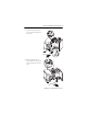
ControlLogix SERCOS interface Module 5 1. Align the circuit board with the top and bottom guides of the chassis. POWER SERCOS interface OK 2. Slide the module into the chassis. Make sure the top and bottom locking tabs snap into place.
ControlLogix SERCOS interface Module Connect the Fiber Optic Cables ATTENTION ATTENTION You must give a unique address to each drive on the SERCOS ring. If you give 2 drives the same address on the same ring, both drives respond to commanded motion. This could injure people or damage equipment. Under certain conditions, viewing the optical port may expose the eye to hazard.
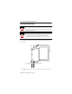
ControlLogix SERCOS interface Module 7 2. Insert each fiber optic cable into the appropriate port and screw on finger tight. The cable that emits light is the transmitter. Any break in the ring disables the SERCOS network and creates a warning a on the SERCOS Ring Status LED.
ControlLogix SERCOS interface Module Interpret the LED Indicators SERCOS Communication Phase Status (CP) Indicator SERCOS Ring Status Indicator CP Module Health and Communication Status (OK) Indicator OK Table 1 SERCOS Communication Phase Status (CP) Indicator State Description Solid Orange Phase -1: Autobaud detection in progress. OFF Phase 0: looking for a closed ring. Flashing Red Phase 1: looking for active nodes. Alternating Red/Green Phase 2: configuring nodes for communication.
ControlLogix SERCOS interface Module 9 Table 2 SERCOS Ring Status Indicator (Continued) State Description Recommended Action Flashing Red The module has detected a setup or configuration fault with the ring. Check your system setup and configuration as follows:. • Ensure drive and axes addresses are correct. • Remove excess axes from ring. • Make sure application program has selected the proper Ring Cycle Period and Baud Rate.
ControlLogix SERCOS interface Module Table 3 Module Health and Communication Status (OK) Indicator State Description Recommended Action Off The module is not operating. • Apply chassis power. • Verify the module is completely inserted into the chassis and backplane. Flashing Green The module has passed internal diagnostics, but has not established active communications. None, if you have not configured the module. Solid Green • Data is being exchanged. None. The module is ready for action.
ControlLogix SERCOS interface Module 11 Remove the Module from the Chassis, If Required WARNING When you insert or remove the module while backplane power is on, an electrical arc can occur. This could cause an explosion in hazardous location installations. Be sure that power is removed or the area is nonhazardous before proceeding. Repeated electrical arcing causes excessive wear to contacts on both the module and its mating connector.
ControlLogix SERCOS interface Module Fiber Optic Cables ATTENTION Under certain conditions, viewing the optical port may expose the eye to hazard. When viewed under some conditions, the optical port may expose the eye beyond the maximum permissible exposure recommended in ANSI Z136.2, 1993.
ControlLogix SERCOS interface Module 13 Table 4 Choose a Plastic Fiber Optic Cable (Continued) For use in: Use this type of plastic cable: Length in meters (inches) Allen-Bradley Catalog Number harsh environment nylon jacketed 1 m, (39 in) 2090-SCNP1-0 3 m, (118 in) 2090-SCNP3-0 5 m (197 in) 2090-SCNP5-0 8 m (315 in) 2090-SCNP8-0 10 m (394 in) 2090-SCNP10-0 15 m (591 in) 2090-SCNP15-0 20 m (787 in) 2090-SCNP20-0 25 m (984 in) 2090-SCNP25-0 32 m (1260 in) 2090-SCNP32-0 Table 5 Choose
ControlLogix SERCOS interface Module Care and Handling of Fiber Optic Cables ATTENTION When you handle these components, take normal precautions to prevent damage and/or degradation by electrostatic discharge (ESD). The small junction size of these components increases their susceptibility to damage from ESD. Good system performance depends on clean port optics and cable ferrules, which keeps dust and small particles from blocking the optic path.
ControlLogix SERCOS interface Module 15 Specifications Description Value Power Dissipation 5.0W Backplane Current 760 mA @ 5.
ControlLogix SERCOS interface Module Description Value Number of Drives 1756-M03SE Up To 3 SERCOS interface drives 1756-M08SE Up to 8 SERCOS interface drives 1756-M16SE Up to 16 SERCOS interface drives 1756-M08SEG Up to 8 SERCOS interface drives. You must use drives that are Extended Pack Profile compliant.
ControlLogix SERCOS interface Module 17 Description Value Glass Fiber Optic Cable Transmission Range 1-200 meters Core Diameter 200μm ± 4μm Cladding Diameter 230μm + 0 / − 10μm Cable Attenuation 6.0 dB/km @ 820nm Operating Temperature -20 to 85° C Connector F-SMA standard screw-type connector Bend Radius 2.5cm Certifications When marked, the module has the following certifications. See the Product Certification link at www.ab.
ControlLogix SERCOS interface Module Environment and Enclosure Information ATTENTION Environment and Enclosure This equipment is intended for use in a Pollution Degree 2 industrial environment, in overvoltage Category II applications (as defined in IEC publication 60664-1), at altitudes up to 2000 meters without derating. This equipment is considered Group 1, Class A industrial equipment according to IEC/CISPR Publication 11.
ControlLogix SERCOS interface Module 19 North American Hazardous Location Approval The following information applies when operating this equipment in hazardous locations: Informations sur l'utilisation de cet équipement en environnements dangereux: Products marked "CL I, DIV 2, GP A, B, C, D" are suitable for use in Class I Division 2 Groups A, B, C, D, Hazardous Locations and nonhazardous locations only.
Rockwell Automation Support Rockwell Automation provides technical information on the web to assist you in using its products. At http://support.rockwellautomation.com, you can find technical manuals, a knowledge base of FAQs, technical and application notes, sample code and links to software service packs, and a MySupport feature that you can customize to make the best use of these tools.