Installation Instructions SSI Servo Module (Catalog Number 1756-M02AS) The Synchronous Serial Interface (SSI) Servo Module mounts in a ControlLogix™ chassis and uses a removable terminal block (RTB) to connect all field-side wiring. Before you install your module you should have: • installed and grounded a 1756 chassis and power supply. • ordered and received an RTB and its components for your application.
SSI Servo Module Important User Information Solid state equipment has operational characteristics differing from those of electromechanical equipment. Safety Guidelines for the Application, Installation and Maintenance of Solid State Controls (Publication SGI-1.1 available from your local Rockwell Automation sales office or online at http://www.ab.com/manuals/gi) describes some important differences between solid state equipment and hard-wired electromechanical devices.
SSI Servo Module 3 Environment and Enclosure ATTENTION This equipment is intended for use in a Pollution Degree 2 industrial environment, in overvoltage Category II applications (as defined in IEC publication 60664-1), at altitudes up to 2000 meters without derating. This equipment is considered Group 1, Class A industrial equipment according to IEC/CISPR Publication 11.
SSI Servo Module Removal and Insertion Under Power WARNING When you insert or remove the module while backplane power is on, an electrical arc can occur. This could cause an explosion in hazardous location installations. Be sure that power is removed or the area is nonhazardous before proceeding. Repeated electrical arcing causes excessive wear to contacts on both the module and its mating connector. Worn contacts may create electrical resistance that can affect module operation.
SSI Servo Module 5 Identifying Module Components You received two components with your order: • 1756-M02AS module • RTB door label If you did not receive these components, contact your Rockwell Automation representative. This module mounts in a 1756 chassis and uses a separately-ordered RTB or a Bulletin 1492 Interface Module (IFM)(1) to connect all field-side wiring.
SSI Servo Module Installing the Module You can install or remove the module while chassis power is applied. WARNING When you insert or remove the module while backplane power is on, an electrical arc can occur. This could cause an explosion in hazardous location installations. Be sure that power is removed or the area is nonhazardous before proceeding. Repeated electrical arcing causes excessive wear to contacts on both the module and its mating connector.
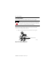
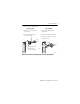
SSI Servo Module 7 2. Slide the module into the chassis until module tabs ‘click’. Locking Tab 20862-M Figure 2 Module Locking Tabs Keying the Module and Removable Terminal Block/Interface Module Use the wedge-shaped keying tabs and U-shaped keying bands to prevent connecting the wrong wires to your module. Key positions on the module that correspond to unkeyed positions on the RTB. For example, if you key the first position on the module, leave the first position on the RTB unkeyed. 1.
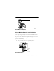
SSI Servo Module 2. Push the band until it snaps in place. 3. To key the RTB or IFM, insert the wedge-shaped tab with rounded edge first, as shown. Wedge-shaped tab 20851–M Figure 4 Keying Band 4. Push the tab until it stops. Reposition the tabs to rekey future module applications. Wiring a Removable Terminal Block (RTB) Your 1756-M02AS module uses two types of RTBs (each RTB comes with housing) to connect wiring.
SSI Servo Module 9 Connect the wires as shown below. Spring Clamp RTB Cage Clamp RTB 1. Strip 7/16 inch (11mm) maximum length of wire. 1. Strip 3/8 inch (9.5mm) maximum length of wire. 2. Insert the screwdriver into the inner hole of the RTB. 2. Insert the wire into the open terminal. 3. Turn the screw clockwise to close the terminal on the wire. 3. Insert the wire into the open terminal and remove the screwdriver.
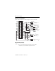
SSI Servo Module Wiring to a Servo Module Use the wiring example in the following figure to wire to your module. +OUT-0 -OUT-0 +ENABLE-0 -ENABLE-0 DRVFLT-0 CHASSIS IN_COM HOME-0. REG24V-0 REG5V-0 +OK CHASSIS +CLOCK-0 -CLOCK-0 +DATA-0 -DATA-0 SSI COM CHASSIS. +OUT-1 -OUT-1 +ENABLE-1 -ENABLE-1 DRVFLT-1 CHASSIS IN_COM HOME-1. REG24V-1 REG5V-1 -OK CHASSIS +CLOCK-1 -CLOCK-1 +DATA-1 -DATA-1 SSI COM CHASSIS.
SSI Servo Module 11 Wiring Registration Sensors The registration inputs to the servo module can support 24V dc or 5V dc registration sensors. These inputs should be wired to receive source current from the sensor. Current sinking sensor configurations are not allowed because the registration input common (IN_ COM) is shared with the other 24V dc servo module inputs.
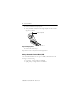
SSI Servo Module Wiring the Home Limit Switch Input The home limit switch inputs to the servo module are designed for 24V dc nominal operation. These inputs should be wired for current sourcing operation. 24 V dc Power Supply + – From 1756-M02AS HOME IN_COM General cable C0720 43396 Figure 9 Home Limit Switch Input Wiring the OK Contacts A set of isolated solid- state OK relay contacts is provided for optional interface to an E- stop string, which controls power to the associated pumps.
SSI Servo Module 13 Assembling the Removable Terminal Block and the Housing 1. Align the grooves at the bottom of the housing with the side edges of the RTB. Groove Side edge of the RTB Groove Strain relief area Side edge of the RTB 2. Slide the RTB into the housing until it snaps into place.
SSI Servo Module 1. Align the module and RTB guides to make sure the module will seat properly. 2. Press quickly and evenly to seat the RTB until the latches snap into place. Locking tab Module guide 20853–M RTB guides 20854–M 3. To lock the RTB on the module, slide the locking tab down.
SSI Servo Module 15 The table below provides an explanation of the OK indicator. If the OK LED displays: The module status is: Take this action: Off The module is not operating. • Apply chassis power. • Verify the module is completely inserted in chassis and backplane. Flashing green light Steady green light • None, if you have not configured the module. The module has passed internal diagnostics, but it is not communicating axis data over the backplane.
SSI Servo Module If the OK LED displays: The module status is: Steady red light One of the following: • A potential nonrecoverable fault has occurred. Take this action: • Reboot the module. • If the solid red persists, replace the module. • The OK contact has opened. Module Status Using the FDBK Indicator 2 AXIS SERVO / SSI Feedback indicators CH0 CH1 FDBK FDBK DRIVE DRIVE OK Figure 14 FDBK Indicator LED The table below provides an explanation of the FDBK indicator.
SSI Servo Module 17 If the FDBK LED displays: The module status is: Take this action: Flashing red light The axis servo loop error tolerance has been exceeded. • Correct the source of the problem. An axis SSI feedback fault has occurred. • Correct the source of the problem by checking the SSI device and power connections. • Clear the servo fault condition using the Motion Axis Fault Reset instruction. • Resume normal operation.
SSI Servo Module The table below provides an explanation of the DRIVE indicator. If the DRIVE LED displays: The module status is: Off One of the following: • The axis is not used. • The axis is a position- only axis type. Take this action: • None, if the axis is not used or is a position- only type. • Otherwise, make sure the module is configured, an axis tag has been associated with the module, and the axis type is servo. Flashing green light The axis drive is in the normal disabled state. None.
SSI Servo Module 19 If the DRIVE LED displays: The module status is: Flashing red light The axis drive output is in the shutdown state. Take this action: • Check for faults that may have generated this state. • Execute the Motion Axis Shutdown Reset instruction. • Resume normal operation. Steady red light The axis drive is faulted. • Check the drive status. • Clear the Drive Fault condition at the drive. • Clear the servo fault condition using the Motion Axis Fault Reset instruction.
SSI Servo Module You must remove the RTB before removing the module. 1. Unlock the locking tab at the top of the module. 2. Open the RTB door and pull the RTB off the module. 42517 20855–M Figure 16 Removing the RTB Removing the Module 1. Push in top and bottom locking tabs. 20856–M Figure 17 Removing the Module Publication 1756-IN595A-EN-P - March 2004 2. Pull module out of the chassis.
SSI Servo Module 21 1756-M02AS Specifications Number of axes Servo loop Type External Drive = Torque External Drive = Velocity or Hydraulic Gain resolution Absolute position range Rate Update Period 2 axes maximum Position Loop: PID with Velocity Feedforward Velocity Loop: PI with Accel Feedforwrd (nested); with Directional Scaling and Friction Compensation Position Loop: PID with Velocity Feedforward and Accel Feedforward with Directional Scaling and Friction Compensation Velocity Loop: N/A (handled b
SSI Servo Module Registration inputs Type 24V dc input voltage Maximum Minimum on Maximum off 5V dc input voltage Maximum Minimum on Maximum off Input impedance 24V dc input 5V dc input Response time (position latched) Optically isolated, current sinking input +24V dc nominal 26. 4V dc 18. 5V dc 3.5V dc +5V dc nominal 5.5V dc 3.7V dc 1.5V dc 9.5 kΩ 1.
SSI Servo Module 23 Isolation Voltage User to System 30V continuous RTB keying User-defined Field wiring arm 36-position RTB (1756-TBCH or -TBS6H)(1) RTB screw torque (cage clamp) 4.4 inch-pounds (0.4Nm) maximum Conductors Wire size Category Screwdriver blade width for RTB #22 to #14 AWG (0.324 to 2.08 sq. mm) stranded(1) 3/ 64 inch (1.2 mm) insulation maximum 2(2) 1/8 inch (3.
SSI Servo Module ESD Immunity IEC 61000-4-2: 6kV contact discharges 8kV air discharges Radiated RF Immunity IEC 61000-4-3: 10V/m with 1kHz sine-wave 80%AM from 80MHz to 2000MHz 10V/m with 200Hz 50% Pulse 100%AM at 900Mhz EFT/B Immunity IEC 61000-4-4: ±2kV at 5kHz on signal ports Surge Transient Immunity IEC 61000-4-5: +2kV line-earth (CM) on shielded ports Conducted RF Immunity IEC 61000-4-6: 10Vrms with 1kHz sine-wave 80%AM from 150kHz to 80MHz Enclosure Type Rating None (open-style) Certifi
SSI Servo Module 25 The following information applies when operating this equipment in hazardous locations: Informations sur l’utilisation de cet équipement en environnements dangereux: Products marked “CL I, DIV 2, GP A, B, C, D” are suitable for use in Class I Division 2 Groups A, B, C, D, Hazardous Locations and nonhazardous locations only. Each product is supplied with markings on the rating nameplate indicating the hazardous location temperature code.
Rockwell Automation Support Rockwell Automation provides technical information on the web to assist you in using our products. At http://support.rockwellautomation.com, you can find technical manuals, a knowledge base of FAQs, technical and application notes, sample code and links to software service packs, and a MySupport feature that you can customize to make the best use of these tools.