Installation Instructions Analog Encoder (AE) Servo Module (Catalog Number 1756-M02AE) The Analog Encoder (AE) Servo Module mounts in a ControlLogix™ chassis and uses a removable terminal block (RTB) to connect all field-side wiring. Before you install your module you should have: • installed and grounded a 1756 chassis and power supply. • ordered and received an RTB and its components for your application.
Analog Encoder (AE) Servo Module Preventing Electrostatic Discharge WARNING ! Electrostatic discharge can damage the servo board if you touch the circuitry or connector pins without taking precautions. Follow these guidelines when you handle the servo board: • Touch a grounded object to discharge potential static. • Wear an approved grounding wrist strap. • Do not touch the connector or connector pins on the servo board. • Do not touch circuit components inside the servo board.
Analog Encoder (AE) Servo Module 3 Removing and Inserting Under Power (RIUP) WARNING ! This module is designed so you can remove and insert it under backplane power and field-side power. When you remove or insert a module while field-side power is applied, you can cause an electrical arc. An electrical arc can cause personal injury or property damage because it can: • Send an erroneous signal to your system field devices causing unintended machine motion or loss of process control.
Analog Encoder (AE) Servo Module Low Voltage Directive This product is tested to meet Council Directive 73/23/EEC Low Voltage, by applying the safety requirements of EN 61131-2 Programmable Controllers, Part 2 - Equipment Requirements and Test. For specific information required by EN 61131-2, see the appropriate sections in this publication, as well as the following Allen-Bradley publications: • Industrial Automation Wiring and Grounding Guidelines publication 1770-4.
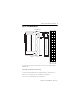
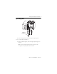
Analog Encoder (AE) Servo Module 5 Figure 1 1756-M02AE Module RTB door label 1756-M02AE module 2 2 Axis Servo +OUT-0 4 -OUT-0 6 1 +OUT-1 3 -OUT-1 5 +ENABLE-0 +ENABLE-1 8 -ENABLE-0 10 DRVFLT-0 12 CHASSIS 14 IN_COM 16 HOME-0 18 REG24V-0 20 REG5V-0 22 +OK 24 CHASSIS 26 +CHA-0 28 -CHA-0 30 +CHB-0 32 Front view Side view -CHB-0 34 +CHZ-0 36 7 -ENABLE-1 9 DRVFLT-1 11 CHASSIS 13 IN_COM 15 HOME-1 17 REG24V-1 19 REG5V-1 21 -OK 23 CHASSIS 25 +CHA-1 27 -CHA-1 29 +CHB-1 31 -CHB-1 33 +CHZ-1 35 -CHZ-0 -CHZ-1 1
Analog Encoder (AE) Servo Module • 1756-TBCH 36-position cage clamp RTB • 1756-TBS6H 36-position spring clamp RTB You received the following components with your RTB: • 1756-TBH standard-depth RTB housing • wedge-shaped keying tabs and U-shaped keying bands • RTB door label Installing the Module WARNING ! When you remove or insert an RTB with field-side power applied, unintended machine motion or loss of process control can occur. Exercise extreme caution when power is applied.
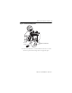
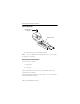
Analog Encoder (AE) Servo Module 7 Figure 2 Circuit Board Alignment POWER Printed circuit board 2. Push evenly and firmly to seat the module in the chassis. It is seated when the top and bottom locking tabs have snapped into place.
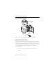
Analog Encoder (AE) Servo Module Figure 3 Module Locking Tabs Locking tab POWER Note: The 1756 chassis provides grounding for your module. Keying the Removable Terminal Block To identify the RTB that belongs with each module, you can use a module keying pattern. First, you can create a unique keying pattern for your module using the U-shaped keying bands that you received with your RTB. Then you can use the keying tabs to key the RTB with the same pattern as the module.
Analog Encoder (AE) Servo Module 9 Figure 4 Keying Band POWER U-shaped keying band 2. Push the keying band onto the module until it snaps into place. To key your removable terminal block: 1. With the rounded edge first, insert the wedge-shaped keying tab on the RTB.
Analog Encoder (AE) Servo Module Figure 5 Keying Tab. Wedge-shaped keying tab Bottom of RTB 2. Push the keying tab onto the RTB until it stops. Note: To use the RTB in future module applications, you can reposition the keying tabs on the RTB. Wiring a Removable Terminal Block There are two types of RTBs: • spring clamp • cage clamp This section describes how to wire each type of RTB and shows wiring examples for the AE module. Wire the RTB before installing it onto the module. Use a 1/8 inch (3.
Analog Encoder (AE) Servo Module 11 Wiring a Spring Clamp RTB To wire a spring clamp RTB: 1. Strip a maximum of 7/16 inch (11mm) of insulation from the end of your wire. 2. Insert the screwdriver into the outer hole of the RTB. 3. Insert the wire into the open terminal and remove the screwdriver. Figure 6 Strain Relief Area Strain Relief Area 4. After you complete field-side wiring, secure the wires in the strain relief area with a cable-tie. Wiring a Cage Clamp RTB To wire a cage clamp RTB: 1.
Analog Encoder (AE) Servo Module 3. Turn the screw clockwise to close the terminal on the wire. Use 5 lb-in. (0.5 Nm) maximum torque Figure 7 Closing Wire Terminal. Strain Relief Area 4. After you complete field-side wiring, secure the wires in the strain relief area with a cable-tie.
Analog Encoder (AE) Servo Module 13 Wiring Examples Figure 8 Wiring to a servo module RTB 2 1 4 3 +OUT-0 +OUT-1 6 5 8 7 10 9 +ENABLE-0 To servo drive General Cable C0721 To servo drive +ENABLE-1 -ENABLE-0 -ENABLE-1 DRVFLT-0 DRVFLT-1 12 11 14 13 16 15 CHASSIS CHASSIS IN_COM IN_COM HOME-0 General Cable C0720 To home limit switch General Cable C0720 To registration sensor HOME-1 18 17 20 19 REG24V-0 REG24V-1 REG5V-0 REG5V-1 22 21 24 23 26 25 28 27 30 29 32
Analog Encoder (AE) Servo Module Figure 9 Wiring to a 1394 Servo Drive (in Torque Mode only) Servo Module RTB +OUT 1 -OUT 1 +ENABLE 1 -ENABLE 1 DRVFLT 1 CHASSIS IN_COM HOME 1 REG24V 1 REG5V 1 -OK CHASSIS +CHA 1 -CHA 1 +CHB 1 -CHB 1 +CHZ 1 -CHZ 1 +OUT 0 -OUT 0 +ENABLE 0 -ENABLE 0 DRVFLT 0 CHASSIS IN_COM HOME 0 REG24V 0 REG5V 0 +OK CHASSIS +CHA 0 -CHA 0 +CHB 0 -CHB 0 +CHZ 0 -CHZ 0 RED BLK WHT BLK RED BLK A 1756-M02AE RED OK+ BLK OK- OK 5V DC Field Power Supply 1394CCAExx WHT BLK RED BLK GRN BLK
Analog Encoder (AE) Servo Module 15 Figure 10 The 1394-CFLAExx Cable Wiring Diagram ENABLE/DRIVE FAULT - AXIS 0 3.0 in. 7 1 12 6 Individually Jacketed Pairs AXIS 0 M02AE - OK 1394-CFLAE 5V ENC PWR - AXIS 0 1756-M02AE 1.0 in. 5.0 in. Note: The 1394-CFLAE cable is available in 1, 3, 8, and 15 meter lengths.
Analog Encoder (AE) Servo Module Figure 11 Pinouts for the 1394-CFLAE +5V +5VCOM 3 9 RED 22GA BLACK 22GA DRAIN CHANNEL A HIGH CHANNEL A LOW CHANNEL B HIGH CHANNEL B LOW CHANNEL Z HIGH CHANNEL Z LOW 4 10 5 11 6 12 ORANGE 22GA WHT/ORG 22GA YELLOW 22GA WHT/YEL 22GA GREEN 22GA WHT/GRN 22GA DRAIN VREF+ TREF+ VREFTREF- 1 2 7 8 (DROK-0) (24V EN COM) (24V) (AX_-ENABLE) BLUE 22GA WHT/BLU 22GA DRAIN VIOLET 22GA WHT/VIO 22GA GRAY 22GA WHT/GRY 22GA DRAIN TO SYSTEM FAULT STRING RED 22GA BLACK 22GA DRAIN
Analog Encoder (AE) Servo Module 17 Figure 12 Wiring to an Ultra 100 Series Drive J1 to 50-pin Terminal Block (Kit P/N 9109-1391) 24 VDC Field Power Supply 24 VDC 24 VCOM From 1756-M02AE General Cable C0720 J1-5 J1-26 J1-24 J1-6 J1-13 Ultra 100 Series Digital Servo Drive 24VDC 24VDC READY+ 24VCOM 24VCOM +OUT J1-22 COMMAND+ -OUT J1-23 COMMAND- P/N 9109-1369-003 +ENABLE From 1756-M02AE General Cable C0721 -ENABLE J1-20 ENABLE DRVFLT J1-25 READY- Interface Cable J1 IN_COM From 1756-M02AE
Analog Encoder (AE) Servo Module Figure 13 Wiring to an Ultra 200 Series Drive J1 to 50-pin Terminal Block (Kit P/N 9109-1391) Ultra 200 Series Digital Servo Drive J1-5 24VDC J1-24 READY+ J1-6 or 13 24VCOM From 1756-M02AE General Cable C0720 +OUT J1-22 COMMAND+ -OUT J1-23 COMMAND- P/N 9109-1369-003 +ENABLE From 1756-M02AE General Cable C0721 -ENABLE J1-20 ENABLE DRVFLT J1-25 READY- Interface Cable J1 IN_COM From 1756-M02AE +CHA J1-7 AOUT+ -CHA J1-8 AOUT- +CHB General Cable C0722
Analog Encoder (AE) Servo Module 19 Figure 15 Pinouts for1398-CFLAExx Cable WHT/ORG 22GA WHT/YEL 22GA DRAIN TAN 28GA Wires Stripped Back .25 in.
Analog Encoder (AE) Servo Module Wiring Registration Sensors The registration inputs to the servo module can support 24V or 5V registration sensors. These inputs must be wired to receive source current from the sensor. Only use sourcing type registration sensors. Current sinking sensor configurations are not allowed because the registration input common (IN_COM) is shared with the other 24V servo module inputs.
Analog Encoder (AE) Servo Module 21 Wiring the Home Limit Switch Input The home limit switch inputs to the servo module are designed for 24V nominal operation. These inputs should be wired for current sourcing operation. Figure 18 Home Limit Switch 24 VDC Field Power Supply + - From 1756-M02AE General Cable C0720 HOME IN_COM Wiring the OK Contacts A set of isolated solid-state OK relay contacts is provided for optional interface to an E-stop string, which controls power to the associated drives.
Analog Encoder (AE) Servo Module Figure 19 OK Relay Pilot Duty Application Wiring 24 VDC Field Power Supply + - OK Relay From 1756-M02AE +OK General Cable C0720 + 24 VDC Field Power Supply -OK OK Relay Contacts +OK Start Stop CR1 CR1 To User's circuitry M1 - IMPORTANT CR1 -OK When the OK Relay is loaded with an inductive load, use a counter-EMF suppression diode across the load. The maximum rating of the OK relay contacts must not exceed 60V DC.
Analog Encoder (AE) Servo Module 23 Figure 20 RTB and Housing. Groove Side edge of RTB Groove Strain relief area Side edge of RTB 1756-TBCH RTB shown for reference Installing the Removable Terminal Block onto the Module WARNING ! WARNING ! A shock hazard exists. If the RTB is installed onto the module while the field-side power is applied, the RTB is electrically live. Do not touch the RTB terminals. Failure to observe this caution can cause personal injury.
Analog Encoder (AE) Servo Module • field-side wiring of the RTB has been completed. • the RTB housing is snapped into place on the RTB. • the RTB housing door is closed. • the locking tab at the top of the module is unlocked. To install the removable terminal block onto the module: 1. Align the top, bottom, and left side guides of the RTB with the guides on the module. Figure 21 Aligning RTB Top guide POWER Bottom guide Left side guides 2.
Analog Encoder (AE) Servo Module 25 Figure 22 Locking Tabs POWER Locking tab Checking the LED Indicators The module provides bi-colored LED indicators to show individual drive and feedback status for both axes and a single bi-colored LED for module OK.
Analog Encoder (AE) Servo Module Figure 23 1756-M02AE Module LEDs 2 AXIS SERVO CH 0 CH 1 FDBK FDBK DRIVE DRIVE OK During power up, the module completes an indicator test. The OK indicator turns red for 1 second and then turns to flashing green if the module passes all its self tests. This completes the installation of the module. Understanding Module Status Using the OK Indicator If the OK LED displays: Then the module status is: Off The module is not operating. • Apply chassis power.
Analog Encoder (AE) Servo Module 27 If the OK LED displays: Then the module status is: Take this action: Steady green light • Axis data is being exchanged with the module. • The module us in the normal operating state. None. The module is ready for action. Flashing red light • A major recoverable failure has occurred. • A communication fault, timer fault, or NVS update is in progress. • The OK contact has opened. If an NVS update is in progress, complete the NVS update.
Analog Encoder (AE) Servo Module If the FDBK LED displays: Then the module status is: Take this action: Steady green light The axis is in the normal servo loop active state. None. The servo can may be changed by executing motion instructions. Flashing red light The axis servo loop error tolerance has been exceeded. • Correct the source of the problem. • Clear the servo fault condition using the Motion Axis Fault Reset instruction. • Resume normal operation.
Analog Encoder (AE) Servo Module 29 If the DRIVE LED displays: Then the module status is: Take this action: Steady green light The axis drive is in the normal enabled state. None. The servo axis state can be changed by executing motion instructions. Flashing red light The axis drive output is in the shutdown state. • Check for faults that may have generated this state. • Execute the Shutdown Reset motion instruction. • Resume normal operation. Solid red light The axis drive is faulted.
Analog Encoder (AE) Servo Module When you connect or disconnect the RTB with field side power applied, an electrical arc can occur. This could cause an explosion in hazardous location installations. Be sure that all sources of power are removed or the area is nonhazardous before proceeding. WARNING ! You must remove the RTB before you can remove the module. To remove the RTB from the module: 1. Unlock the locking tab at the top of the module. 2. Open the RTB door using the bottom tab. 3.
Analog Encoder (AE) Servo Module 31 Removing the Module from the Chassis To remove the module from the chassis: 1. If the RTB is on the module, unlock the RTB and remove it. For more information, refer to Removing the Removable Terminal Block from the Module. 2. Push in and hold the top and bottom locking tabs on the module. Figure 25 Hold Locking Tabs POW ER 3. Pull the module out of the chassis.
Analog Encoder (AE) Servo Module Figure 26 Pulling Module Out POWER Module Specifications Number of axes 2 axes maximum Servo loop Type Gain resolution Absolute position range Rate Nested PI digital position and velocity servo 32-bit floating point ±1,000,000,000 encoder counts 5 kHz Module location 1756 ControlLogix chassis Module keying Electronic Power dissipation 5.5W maximum Backplane current 5.1V dc @ 700 mA and 24V dc @ 2.
Analog Encoder (AE) Servo Module 33 Registration inputs Type 24V input voltage Maximum Minimum on Maximum off 5V input voltage Maximum Minimum on Maximum off Input impedance 24V input 5V input Response time (position latched) Optically isolated, current sinking input +24V dc nominal 26.4V 18.5V 3.5V +5V dc nominal 5.5V 3.7V 1.5V 9.5 kOhms 1.2 kOhms 1µs All other inputs Type Input voltage Maximum Minimum on Maximum off Input impedance Optically isolated, current sinking input +24V dc nominal 26.4V 17.
Analog Encoder (AE) Servo Module Environmental conditions Operating temperature Storage temperature Relative humidity 0 to 60ºC (32 to 140ºF) -40 to 85ºC (-40 to 185ºF) 5 to 95% noncondensing Agency Certifications When product is marked Listed Industrial Control Equipment Certified Process Control Equipment Certified Class I, Division 2, Group A, B, C, D Marked for applicable directives Marked for all applicable acts N223 1) 2) 3) Maximum wire size will require the extended depth RTB housing (1756-
Analog Encoder (AE) Servo Module 35 code of the system. Combinations of equipment in your system are subject to investigation by the local Authority Having Jurisdiction at the time of installation. WARNING ! EXPLOSION HAZARD – • Do not disconnect equipment unless power has been removed or the area is known to be nonhazardous. • Do not disconnect connections to this equipment unless power has been removed or the area is known to be nonhazardous.
Analog Encoder (AE) Servo Module Informations sur l’utilisation de cet équipement en environnements dangereux: RISQUE D’EXPLOSION – • Couper le courant ou s’assurer que l’environnement est classé non dangereux avant de débrancher l'équipement. • Couper le courant ou s'assurer que l’environnement est classé non dangereux avant de débrancher les connecteurs.
Analog Encoder (AE) Servo Module 37 NOTES: Publication 1756-IN047D-EN-P - March 2001
Analog Encoder (AE) Servo Module NOTES: Publication 1756-IN047D-EN-P - March 2001
Analog Encoder (AE) Servo Module 39 NOTES: Publication 1756-IN047D-EN-P - March 2001
ControlLogix is a trademark of Allen-Bradley Company, Inc., a Rockwell International company. Publication 1756-IN047D-EN-P - March 2001 Supersedes Publication 1756-IN047C-EN-P - November 2000 PN957536-48 © 2001 Rockwell International Corporation.