Installation Instructions ControlLogix Controller and Memory Board Catalog Numbers 1756-L1, 1756-L1M1, 1756-L1M2, 1756-L1M3, 1756-L55, 1756-L55M12, 1756-L55M13, 1756-L55M14, 1756-L55M16, 1756-L55M22, 1756-L55M23, 1756-L55M24, 1756-L61, 1756-L62, 1756-L63, 1756-L64, 1756-L65, 1756-M1, 1756-M2, 1756-M3, 1756-M12, 1756-M13, 1756-M14, 1756-M16, 1756-M22, 1756-M23, 1756-M24, 1784-CF64, 1784-CF128 Topic Page Important User Information 3 Explosion Hazards 4 Preventing Electrostatic Discharge 4 Removing M
ControlLogix Controller and Memory Board Topic Page Required System Components 12 Firmware Revisions 14 Preparing the Chassis 16 Remove the Controller from the Chassis 16 Installing a Memory Board on a ControlLogix5550 or ControlLogix5555 Controller 17 Installing a CompactFlash Card in a Controller 22 Connecting a Battery 25 Installing the Controller into the Chassis 28 Check the BAT Status Indicator 29 Checking the OK Status Indicator 30 Update the Controller 32 Connecting a Seria
ControlLogix Controller and Memory Board 3 Important User Information Solid state equipment has operational characteristics differing from those of electromechanical equipment. Safety Guidelines for the Application, Installation and Maintenance of Solid State Controls (Publication SGI-1.1 available from your local Rockwell Automation sales office or online at http://literature.rockwellautomation.
ControlLogix Controller and Memory Board Explosion Hazards WARNING An electrical arc can occur if you: • insert or remove the CompactFlash card. • insert or remove the controller while backplane power is on. • connect or disconnect the battery. • connect or disconnect the serial cable with power applied to this module or the serial device on the other end of the cable. This could cause an explosion in hazardous location installations.
ControlLogix Controller and Memory Board 5 Environment and Enclosure ATTENTION This equipment is intended for use in a Pollution Degree 2 industrial environment, in overvoltage Category II applications (as defined in IEC publication 60664-1), at altitudes up to 2000 m (6561 ft) without derating. This equipment is considered Group 1, Class A industrial equipment according to IEC/CISPR Publication 11.
ControlLogix Controller and Memory Board North American Hazardous Location Approval The following information applies when operating this equipment in hazardous locations. Informations sur l’utilisation de cet équipement en environnements dangereux. Products marked "CL I, DIV 2, GP A, B, C, D" are suitable for use in Class I Division 2 Groups A, B, C, D, Hazardous Locations and nonhazardous locations only.
ControlLogix Controller and Memory Board 7 European Hazardous Location Approval European Zone 2 Certification (The following applies when the product bears the Ex or EEx Marking) This equipment is intended for use in potentially explosive atmospheres as defined by European Union Directive 94/9/EC.
ControlLogix Controller and Memory Board Before You Begin Read this section for important information about using these products, noting that this publication covers the products shown in the table. Product Cat. No.
ControlLogix Controller and Memory Board 9 Replace a Suspected Failed Controller To replace a failed controller, do the following. 1. Cycle power to the chassis. 2. Make sure the OK status indicator is solid red, noting that if the OK status indicator is not solid red, the controller does not require replacement. 3.
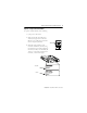
ControlLogix Controller and Memory Board 4. Insert the battery. Series B Series A COMPACT FLASH 1-DCD 2-RXD 3-TXD 4-DTR 5-GND DSR-6 RTS-7 CTS-8 N/C-9 RS232 1 To Insert 1 2 To Eject 1+2 1 2 UP BATTERY DATE 1 2 BATTERY PORT 42523 5. Insert the key, and turn it to the PROG position. 6. Insert the controller into the chassis. 20880 7. Use ControlFlash software to update the firmware of the controller. 8. Download the RSLogix 5000 project to the controller.
ControlLogix Controller and Memory Board 11 Resolving Common Errors IMPORTANT Before you change a memory board, update the controller to a revision that is compatible with the memory board that you intend to install. Make sure you use the correct firmware revision. To resolve common errors, see the following table. For more information on how to avoid these common errors, refer to the Memory Board table or Firmware Revisions section.
ControlLogix Controller and Memory Board Required System Components These components ship with the controller. Component Description Series A controllers: 1756-BA1 battery Series B controllers: 1756-BA2 battery Key You can use these components with the controller. IMPORTANT To maintain memory longer than is available with the battery, this option maintains memory only while the controller is in the chassis. Optional Components Description Controller 1756-CP3 serial cable.
ControlLogix Controller and Memory Board 13 Optional Components Description Controller Component Add nonvolatile memory ControlLogix5550 Not available for this controller. ControlLogix5555 Memory board. ControlLogix5561 ControlLogix5562 ControlLogix5563 ControlLogix5564 ControlLogix5565 1784-CF64 Industrial CompactFlash Card. 31376-M Maintain memory longer than is available with the battery ControlLogix5550 Not available for this controller.
ControlLogix Controller and Memory Board Memory Board Controller Memory Board ControlLogix5550 ControlLogix5555 ControlLogix5561 1756-M1, 1756-M2, 1756-M3 No nonvolatile memory 1756-M12, 1756-M13, 1756-M14, 1756-M16 Nonvolatile memory 1756-M22, 1756-M23, 1756-M24 Do not install a memory board. ControlLogix5562 ControlLogix5563 ControlLogix5564 ControlLogix5565 Firmware Revisions To update the firmware of a controller, install a firmware upgrade kit.
ControlLogix Controller and Memory Board 15 Use the following table to determine which firmware revisions to use with your controller and memory board combination. Controller and Memory Board Combinations Controller and Memory Board Series Use this revision or later 1756-L1 None Any. 1756-L1M1 1756-L1M2 1756-L1M3 1756-L55M12 10.x or later. 1756-L55M13 6.x or later. 1756-L55M14 1756-L55M16 1756-L55M22 10.x or later. 1756-L55M23 8.x or later. 1756-L55M24 1756-L61 1756-L62 1756-L63 A 12.
ControlLogix Controller and Memory Board Preparing the Chassis Before you install a controller: • install a ControlLogix chassis. • install a ControlLogix power supply. Remove the Controller from the Chassis You can install or remove a controller while chassis power is on and the system is operating. If you remove the controller, all the devices owned by the controller go to their configured fault state.
ControlLogix Controller and Memory Board 17 Installing a Memory Board on a ControlLogix5550 or ControlLogix5555 Controller ATTENTION WARNING Before you install or replace the memory board, disconnect the battery from the controller. Otherwise, you may damage the memory board. When you connect or disconnect the battery an electrical arc can occur. This could cause an explosion in hazardous location installations. Be sure that power is removed or the area is nonhazardous before proceeding.
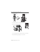
ControlLogix Controller and Memory Board Remove the Side Plate of the Controller 1. Lay the controller on its side with the label facing up. 2. Remove the two screws that attach the side plate to the controller while wearing a grounding wriststrap. 3. Rotate the side plate (A) up and unhook it from the controller, as shown in the figure.
ControlLogix Controller and Memory Board 19 Remove the Existing Memory Board If the controller does not already have a memory board, as shown in the figure, refer to the Install the Memory Board section. 42527 1. Pull the plastic back edge of the controller out slightly to clear the tabs on the memory board. 42526 2. Gently separate and remove the memory board from the controller.
ControlLogix Controller and Memory Board Install the Memory Board 1. Place the memory board over the connector and slide the memory board into the controller. 2 1 1 3 3 Item Description 1 Tab 2 Memory board 3 Slot 40018 2. Pull the plastic back edge of the controller out slightly to clear the tabs of the memory board. 3. Line up the connectors. 4. Place your hands on the boards over the connectors and gently squeeze them together. 5.
ControlLogix Controller and Memory Board 21 Replace the Side Plate 40019 1. Line up the hinge tabs on the side plate with the slots in the plastic housing of the controller. 2. Gently press the side plate against the controller. 3. Replace the screws. Attach Labels To identify which memory board is installed, place the memory board label on the side of the controller.
ControlLogix Controller and Memory Board Installing a CompactFlash Card in a Controller A 1784-CF64 or 1784-CF128 Industrial CompactFlash Card provides nonvolatile memory for a ControlLogix5561, ControlLogix5562, ControlLogix5563, ControlLogix5564, or a ControlLogix5565 controller. Install a CompactFlash Card in a Series A Controller 1. Lay the controller on its side with the front facing to the left. 2. Raise the locking clip all the way up. 3.
ControlLogix Controller and Memory Board 23 Install a CompactFlash Card in a Series B Controller WARNING ATTENTION When you insert or remove the CompactFlash card an electrical arc can occur. This could cause an explosion in hazardous location installations. Be sure that power is removed or the area is nonhazardous before proceeding. If you are not sure of the contents of the CompactFlash card, before you install the card turn the keyswitch of the controller to the PROG position.
ControlLogix Controller and Memory Board Remove a CompactFlash Card from a Series B Controller WARNING When you insert or remove the CompactFlash card an electrical arc can occur. This could cause an explosion in hazardous location installations. Be sure that power is removed or the area is nonhazardous before proceeding. 1. If the OK status indicator is flashing green, wait until it turns solid green.
ControlLogix Controller and Memory Board 25 Connecting a Battery WARNING ATTENTION ATTENTION When you connect or disconnect the battery an electrical arc can occur. This could cause an explosion in hazardous location installations. Be sure that power is removed or the area is nonhazardous before proceeding. For Safety information on the handling of lithium batteries, including handling and disposal of leaking batteries, see Guidelines for Handling Lithium Batteries, publication AG-5-4-NOV04.
ControlLogix Controller and Memory Board Install a Battery in a Series A Controller ATTENTION For a series A controller, connect only a 1756-BA1 battery or a 1756-BATM battery module. Other batteries may damage the controller. 1. Insert and connect the battery as shown. 2. Write the date on the battery label. 3. Attach the label to the inside of the controller door.
ControlLogix Controller and Memory Board 27 Install a Battery in a Series B Controller ATTENTION For a series B controller, connect only a 1756-BA2 battery. Other batteries may damage the controller. 1. Insert the battery with the arrow pointing up as shown. 2. Connect the battery: + Red, - Black. 3. Write the date on the battery label. 4. Attach the label to the inside of the controller door.
ControlLogix Controller and Memory Board Installing the Controller into the Chassis When you install a ControlLogix controller, you can: • place the controller in any slot. • use multiple controllers in the same chassis. You can install or remove a ControlLogix controller while chassis power is on and the system is operating. WARNING When you insert or remove the module while backplane power is on, an electrical arc can occur. This could cause an explosion in hazardous location installations.
ControlLogix Controller and Memory Board 29 Check the BAT Status Indicator 1. Turn on the chassis power. 42525 2. If the BAT status indicator is on, see the following step; if the BAT status indicator is off, see Firmware Revisions. 3. Check that the battery or battery module is correctly connected to the controller. 4. If the BAT status indicator remains on, install another battery. 5.
ControlLogix Controller and Memory Board Checking the OK Status Indicator 42525 1. Check the color of the OK status indicator. If Then Actions Solid green The controller is OK and its firmware has been updated. No further actions are required. However, the revision of firmware must be compatible with your version of RSLogix 5000 software. Flashing red The controller is OK but it requires a firmware update. Go to Firmware Revisions.
ControlLogix Controller and Memory Board 31 3. Determine if the memory board has been replaced with a memory board with a different catalog number. For example, did you replace a 1756-M13 memory board with a 1756-M23 memory board? If Then No The controller is not operational. Contact your Rockwell Automation representative or local distributor. Yes Go to the next step. 4. Reinstall the previous memory board. 5.
ControlLogix Controller and Memory Board Update the Controller IMPORTANT RSLogix 5000 software, version 10.0 or later, lets you update the firmware of a controller as part of the download sequence. To update the controller, download your project and follow the prompts of the software. 1. Connect the controller or chassis to the same network as your workstation. 2. Start ControlFLASH software. 3. Click Next. 4. Select the catalog number of the controller, and click Next. 5.
ControlLogix Controller and Memory Board 33 6. Select the controller, and click OK. 42900 7. Select the revision level to which you want to update the controller and click Next. IMPORTANT If the Revision list is empty, download a new upgrade kit. Some older upgrade kits do not work with new controllers. For more information, refer to the ControlFlash Firmware Upgrade Kit Quick Start, publication 1756-QS105. 8. To start the update of the controller, click Finish and then click Yes.
ControlLogix Controller and Memory Board Connecting a Serial Cable WARNING If you connect or disconnect the serial cable with power applied to this module or the serial device on the other end of the cable, an electrical arc can occur. This could cause an explosion in hazardous location installations. Make sure that power is removed or the area is nonhazardous before proceeding. Use the serial port for RS-232 communication.
ControlLogix Controller and Memory Board 35 To connect a workstation to the serial port, use one of these cables: • 1756-CP3 serial cable • 1747-CP3 cable from the SLC product family. If you use this cable, the controller door may not close. 1 2 Item Description 1 Workstation end 2 Controller end 42576 If you make your own serial cable, limit the length to 15.2 m (50 ft), wire the connectors as follows, and attach the shield to both connectors.
ControlLogix Controller and Memory Board Interpreting the Status Indicators The following table describes the status indicators. Indicator Status Description RUN Off The controller is in Program or Test mode. See Choosing the Operating Mode of the Controllers. Solid green The controller is in Run mode. See Choosing the Operating Mode of the Controllers. I/O Off •If no devices are in the I/O configuration of the controller, add the required devices to the I/O configuration of the controller.
ControlLogix Controller and Memory Board 37 Indicator Status Description RS232 Off There is no activity. Solid green Data is being received or transmitted. Off For a Series A controller, the controller does not show this indication. Solid green For a Series B controller, during power-down, the controller is saving the project to its internal nonvolatile memory. If the BAT status indicator is solid red before you turn off the power, the BAT status indicator remains solid red even during the save.
ControlLogix Controller and Memory Board Clear a Major Fault 1. Go online with RSLogix 5000 software and get the fault code. 2. Determine what to do next. Fault Type Fault Code Action 1 60 A. Clear the fault. B. Download the project to the controller. C. Return the controller to the Run/Remote Run mode. Follow these steps if the problem persists: A. Before you cycle power to the controller, record the state of the OK and RS232 status indicators. B. Contact Rockwell Automation support. 1 61 A.
ControlLogix Controller and Memory Board 39 Clear a Nonrecoverable Fault 1. Cycle power to the chassis. 2. Determine what to do next: If the OK status indicator is Then Solid green A. Download the project to the controller. B. Return the controller to the Run/Remote Run mode. Flashing red A. Go online with RSLogix 5000 software and clear the major fault. B. Download the project to the controller. C. Return the controller to the Run/Remote Run mode.
ControlLogix Controller and Memory Board Choosing the Operating Mode of the Controllers Do you need to schedule a ControlNet network? Do you want to prevent RSLogix 5000 software from changing the mode? Yes Yes No Do you want to execute the logic in the controller? B No Turn the keyswitch to PROG (Program mode). A Yes Do you want the logic to control the output devices? Yes No No Turn the keyswitch to A PROG and then to REM (Remote Program mode).
ControlLogix Controller and Memory Board 41 Specifications Specifications - ControlLogix Controllers Cat. No. Memory Nonvolatile Memory Data and Logic(1) Yes(2) 1756-L55M22 750 KB 208 KB 1756-L55M23 1.5 MB 1756-L55M24 3.5 MB 1756-L61/A 2 MB 1756-L62/A 4 MB 1756-L63/A 8 MB 1756-L61/B 2 MB 1756-L62/B 4 MB 1756-L63/B 8 MB 1756-L64/B 16 MB 1756-L65/B 32MB Yes Backplane Current @ 5.1V DC @ 24V DC 1.23 A 0.014 A Power Dissipation Thermal Dissipation Weight, approx. 5.6 W 19.
ControlLogix Controller and Memory Board ControlLogix Controller Common Specifications - 1756-L1, 1756-L1M1, 1756-L1M2, 1756-L1M3, 1756-L55, 1756-L55M12, 1756-L55M13, 1756-L55M14, 1756-L55M16, 1756-L55M22, 1756-L55M23, 1756-L55M24, 1756-L61, 1756-L62, 1756-L63, 1756-L64, and 1756-L65 Attribute Value Temperature, operating IEC 60068-2-1 (Test Ad, Operating Cold), IEC 60068-2-2 (Test Bd, Operating Dry Heat), IEC 60068-2-14 (Test Nb, Operating Thermal Shock): • 0 … 60 °C (32…140 °F) Temperature, storage
ControlLogix Controller and Memory Board 43 ControlLogix Controller Common Specifications - 1756-L1, 1756-L1M1, 1756-L1M2, 1756-L1M3, 1756-L55, 1756-L55M12, 1756-L55M13, 1756-L55M14, 1756-L55M16, 1756-L55M22, 1756-L55M23, 1756-L55M24, 1756-L61, 1756-L62, 1756-L63, 1756-L64, and 1756-L65 Attribute Value Conducted RF immunity IEC 61000-4-6: • 10V rms with 1 kHz sine-wave 80% AM from 150 kHz…80 MHz Enclosure type rating None, open style Isolation voltage 30V (continuous), Basic Insulation Type, RS232 to
ControlLogix Controller and Memory Board ControlLogix Memory Board Specifications - 1756-M1, 1756-M2, 1756-M3, 1756-M12, 1756-M13, 1756-M14, 1756-M16, 1756-M22, 1756-M23, and 1756-M24 Attribute Value Temperature, operating EC 60068-2-1 (Test Ad, Operating Cold), IEC 60068-2-2 (Test Bd, Operating Dry Heat), IEC 60068-2-14 (Test Nb, Operating Thermal Shock): • 0 … 60 °C (32…140 °F) Temperature, storage IEC 60068-2-1 (Test Ab, Unpackaged Nonoperating Cold), IEC 60068-2-2 (Test Bb, Unpackaged Nonoperati
ControlLogix Controller and Memory Board 45 Industrial CompactFlash Card Specifications - Industrial CompactFlash Card - 1784-CF64, 1784-CF128 Attribute Value User available memory 64 MB, 128 MB Nonvolatile memory Yes Weight, approx. 14.2 g (0.
ControlLogix Controller and Memory Board Certifications - ControlLogix Controller Certifications(1) Cat. No. Certification Description 1756-L1, 1756-L55 UL UL Listed Industrial Control Equipment. See UL File E65584. CSA CSA Certified Process Control Equipment. See CSA File LR54689C. CSA Certified Process Control Equipment for Class I, Division 2 Group A,B,C,D Hazardous Locations. See CSA File LR69960C. CE European Union 2004/108/IEC EMC Directive, compliant with: • EN 61326-1; Meas./Control/Lab.
ControlLogix Controller and Memory Board 47 Certifications - ControlLogix Controller Certifications(1) Cat. No. 1756-L61, 1756-L62, 1756-L63, 1756-L64, 1756-L65 (1) Certification Description c-UL-us UL Listed Industrial Control Equipment, certified for US and Canada. See UL File E65584. c-UL-us UL Listed for Class I, Division 2 Group A,B,C,D Hazardous Locations, certified for U.S. and Canada. See UL File E194810. CSA CSA Certified Process Control Equipment. See CSA File LR54689C.
ControlLogix Controller and Memory Board Certifications - ControlLogix Memory Board(1) Cat. No. 1756-M1, 1756-M2 1756-M3 1756-M12 1756-M13 1756-M14 1756-M16 1756-M22 1756-M23 1756-M24 (1) Certification Description UR UL Recognized Component Industrial Control Equipment. See UL File E65584. CSA CSA Certified Process Control Equipment. See CSA File LR54689C. CSA Certified Process Control Equipment for Class I, Division 2 Group A,B,C,D Hazardous Locations. See CSA File LR69960C.
ControlLogix Controller and Memory Board 49 Additional Resources These documents contain additional information concerning related Rockwell Automation http://www.ab.com products. Resource Description ControlFLASH Firmware Upgrade Kit Quick Start, publication 1756-QS105 Contains information on how to upgrade and manage module firmware. ControlLogix Controllers User Manual, publication 1756-UM001 Contains information on how to install, configure, program, and operate a ControlLogix system.
ControlLogix Controller and Memory Board Notes: Publication 1756-IN101L-EN-P - June 2008
ControlLogix Controller and Memory Board 51 Notes: Publication 1756-IN101L-EN-P - June 2008
Rockwell Automation Support Rockwell Automation provides technical information on the Web to assist you in using its products. At http://support.rockwellautomation.com, you can find technical manuals, a knowledge base of FAQs, technical and application notes, sample code and links to software service packs, and a MySupport feature that you can customize to make the best use of these tools.