Installation Instructions GuardLogix Controllers Catalog Numbers 1756-L61S, 1756-L62S, 1756-L63S, 1756-LSP Topic Page North American Hazardous Location Approval 3 Environment and Enclosure Information 4 General Safety Information 4 Preventing Electrostatic Discharge 4 Prepare the Chassis 5 Make Sure That You Have All of the Components 5 Install a CompactFlash Card 6 Remove a CompactFlash Card 7 Connect the Battery 8 Install the Controller into the Chassis 9 Check the BAT Status Indi
GuardLogix Controllers Important User Information Solid state equipment has operational characteristics differing from those of electromechanical equipment. Safety Guidelines for the Application, Installation and Maintenance of Solid State Controls (publication SGI-1.1 available from your local Rockwell Automation sales office or online at http://literature.rockwellautomation.com) describes some important differences between solid state equipment and hard-wired electromechanical devices.
GuardLogix Controllers 3 North American Hazardous Location Approval The following information applies when operating this equipment in hazardous locations. Informations sur l’utilisation de cet équipement en environnements dangereux . Products marked “CL I, DIV 2, GP A, B, C, D” are suitable for use in Class I Division 2 Groups A, B, C, D, Hazardous Locations and nonhazardous locations only.
GuardLogix Controllers Environment and Enclosure Information ATTENTION Environment and Enclosure This equipment is intended for use in a Pollution Degree 2 industrial environment, in overvoltage Category II applications (as defined in IEC 60664-1), at altitudes up to 2000 m (6562 ft) without derating. This equipment is considered Group 1, Class A industrial equipment according to IEC/CISPR Publication 11.
GuardLogix Controllers 5 Prepare the Chassis Before you install a controller, follow these preliminary steps. 1. Install a ControlLogix chassis (catalog number 1756-A4/B, 1756-A7/B, 1756-A10/B, or 1756-A17/B) according to the ControlLogix Chassis Installation Instructions, publication 1756-IN080. 2. Install one of the following ControlLogix power supplies according to the corresponding installation instructions.
GuardLogix Controllers Install a CompactFlash Card WARNING ATTENTION When you insert or remove the CompactFlash card an electrical arc can occur. This could cause an explosion in hazardous location installations. Be sure that power is removed or the area is nonhazardous before proceeding. If you are not sure of the contents of the CompactFlash card, before you install the card, turn the keyswitch of the controller to the PROG position.
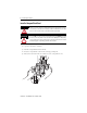
GuardLogix Controllers 7 Remove a CompactFlash Card WARNING When you insert or remove the CompactFlash card an electrical arc can occur. This could cause an explosion in hazardous location installations. Be sure that power is removed or the area is nonhazardous before proceeding. 1. If the OK status indicator is flashing green, wait until it turns solid green.
GuardLogix Controllers Connect the Battery This controller contains a lithium battery, which is intended to be replaced during the life of the product. WARNING When you connect or disconnect the battery, an electrical arc can occur. This could cause an explosion in hazardous location installations. Be sure that power is removed or the area is nonhazardous before proceeding.
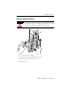
GuardLogix Controllers 9 Install the Controller into the Chassis WARNING When you insert or remove the module while backplane power is on, an electrical arc can occur. This could cause an explosion in hazardous location installations. Be sure that power is removed or the area is nonhazardous before proceeding. Repeated electrical arcing causes excessive wear to contacts on both the module and its mating connector. Worn contact may create electrical resistance that can affect module operation. 1.
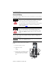
GuardLogix Controllers Check the BAT Status Indicator Follow these steps for both the 1756-L6xS controller and 1756-LSP safety partner. 1. Turn on the chassis power. 2. Check the status of the BAT indicator. If Then Off Go to Update the Controller on page 11. On Go to step 3. BAT Status Indicator 3. Check that the battery is correctly connected to the controller or safety partner. 4. If the BAT status indicator remains on, install another battery. 5.
GuardLogix Controllers 11 Update the Controller Follow these steps for the 1756-L6xS controller. With ControlFlash, version 8 (RSLogix 5000, version 18) software, the 1756-LSP safety partner updates automatically, when the 1756-L6xS controller is updated. 1. Connect the controller or chassis to the same network as your workstation. 2. Start ControlFlash software. 3. Choose Next >. 4. Select the catalog number of the controller and choose Next >. 5. Expand the network until you see the controller.
GuardLogix Controllers 8. To start the update of the controller, click Finish and then click Yes. After the controller is updated, the status dialog box displays ‘Update complete’. 9. Click OK. 10. To close ControlFlash software, click Cancel and then Yes. Connect a Serial Cable WARNING If you connect or disconnect the serial cable with power applied to this module or the serial device on the other end of the cable, an electrical arc can occur.
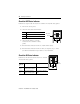
GuardLogix Controllers 13 To connect a workstation to the serial port, use one of these cables: • 1756-CP3 serial cable • 1747-CP3 cable from the SLC product family (If you use this cable, the controller door may not close.) If you make your own serial cable: • limit the length to 15.2 m (50 ft). • wire the connectors as shown. • attach the shield to both connectors.
GuardLogix Controllers Choose the Operating Mode of the Controller IMPORTANT • Controller communication occurs regardless of mode. • All modes produce and consume tags. Do you need to schedule a network? Do you want to prevent RSLogix 5000 software from changing the mode? Yes No Turn the keyswitch to PROG A and then to REM (Remote Program mode).
GuardLogix Controllers WARNING 15 When you connect or disconnect the battery, an electrical arc can occur. This could cause an explosion in hazardous location installations. Be sure that power is removed or the area is nonhazardous before proceeding. Because the GuardLogix controller is a 1oo2 controller (two processors), we strongly recommend that both controller batteries be replaced at the same time. Follow this procedure to replace the battery. 1. Turn on the chassis power.
GuardLogix Controllers General Specifications Cat. No. 1756-L61S 1756-L62S 1756-L63S 1756-LSP Memory - standard tasks 2 MB 4 MB 8 MB N/A Memory - safety task 1 MB 1 MB 3.75 MB (2) Backplane current at 5V DC 1200 mA 1200 mA 1200 mA 1200 mA Backplane current at 24V DC 14 mA 14 mA 14 mA 14 mA Power dissipation 3.5 W 3.5 W 3.5 W 3.5 W Thermal dissipation 11.9 BTU/hr 11.9 BTU/hr 11.9 BTU/hr 11.9 BTU/hr Weight, approx. 0.32 kg (11.3 oz) 0.32 kg (11.3 oz) 0.32 kg (11.
GuardLogix Controllers 17 Environmental Specifications Attribute Value Temperature, operating IEC 60068-2-1 (Test Ad, Operating Cold), IEC 60068-2-2 (Test Bd, Operating Dry Heat), IEC 60068-2-14 (Test Nb, Operating Thermal Shock): • 0…60 °C (32…140 °F) Temperature, storage IEC 60068-2-1 (Test Ab, Un-packaged Non-operating Cold), IEC 60068-2-2 (Test Bb, Un-packaged Non-operating Dry Heat), IEC 60068-2-14 (Test Na, Un-packaged Non-operating Thermal Shock): • -40…85 ° C (-40…185 °F) Relative humidity
GuardLogix Controllers Certifications When marked, the components have the following certifications. See the Product Certification link at http://ab.com for current Declarations of Conformity, Certificates, and other certification details. Certification Description Functional Certified by TÜV: capable of SIL 1 to 3, according to IEC 61508; and PLe/Cat. 4 according to ISO 13849-1 Safety(1) Certified by UL: capable of SIL 3, see UL File E256621.
GuardLogix Controllers 19 Additional Resources Resource Description GuardLogix Controllers User Manual, publication 1756-UM020 Information on configuration and programming specific to the GuardLogix system GuardLogix Controller Systems Safety Reference Manual, publication 1756-RM093 Information on the Safety concept of the GuardLogix controller system GuardLogix Safety Application Instruction Set Reference Manual, publication 1756-RM095 Information on the GuardLogix Safety Application Instruction S
Rockwell Automation Support Rockwell Automation provides technical information on the Web to assist you in using its products. At http://support.rockwellautomation.com, you can find technical manuals, a knowledge base of FAQs, technical and application notes, sample code and links to software service packs, and a MySupport feature that you can customize to make the best use of these tools.