
Owner's manual

Rockwell Automation Publication 1756-UM536A-EN-P - April 2012 77
Appendix C
Alternate Wiring for Non-IEC Type 3 Sensors
The following sections provide recommendations on how to use your counter
module with an open collector sensor that is not IEC compliant.
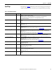
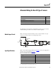
Module Input Circuit
Refer to the input circuit shown below to wire a counter module to an open
collector sensor that requires an external pull-up resistor.
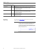
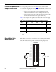
Input Specifications
Refer to the module’s input specifications in Table 8 to choose an appropriate a
pull-up resistor as described on page 78
.
Topic Page
Module Input Circuit 77
Input Specifications 77
Choose a Pull-up Resistor for an Open Collector Sensor 78
Open Collector Wiring without a Resistor 78
V_Supply
R_Pullup
IN-x or CTR-x
Current
Limit
HiSpeed Logic
Opto Coupler
GND-x or CTR GND-x
Module
Display
Table 8 - Counter Module without External Resistor
Voltage across Terminals Input Current @ 25 °C (77 °F)
Off ≤
5V
(1)
(1) 5V or less across the input terminals for a module Off state.
< 1.5 mA
Turn-on at 8.9V 2.5 mA
10V
(2)
(2) 10V minimum required across input terminals for a module On state.
3.8 mA
24V 4.8 mA
30V 5.0 mA