
Owner's manual


Rockwell Automation Publication 1756-UM536A-EN-P - April 2012 33
Install the Counter Module Chapter 3
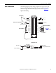
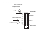
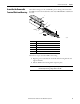
Wire Terminations
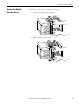
The following diagrams provide wiring examples for the eight counter, eight
input point, 24V high-speed DC isolated, sink/source input module. For
alternate wiring for use with non-IEC Type 3 sensors, refer to Appendix
D.
Figure 12 - Device Wiring
1
3
5
7
019
2111
4131
6151
8171
0291
2212
4232
6252
8272
0392
2313
4333
6353
(+)
(+)
GND-0
GND-1
GND-2
GND-3
CTR-GND-0
GND-4
GND-5
GND-6
GND-7
Not Used
CTR GND-1
CTR GND-2
CTR GND-3
CTR GND-4
5
6
7
7
IN-0
IN-1
IN-2
IN-3
CTR-0
IN-4
IN-5
IN-6
IN-7
Not Used
Not Used
DC-5 (-)
DC (-)
DC-6 (-)
DC-5 (+)
DC-6 (+)
DC (+)
DC-1 (+)
DC-2 (+)
DC-1 (-)
DC-2 (-)
CTR GND-
CTR GND-
CTR GND-
CTR GND-
CTR-1
CTR-2
CTR-3
CTR-4
CTR-5
CTR-6
CTR-7
2
4
6
8
Simplified Schematic
ControlLogix Backplane Interface
Module Display
GND-x or CTR GND-x
IN-x or CTR-x
1756-LSC8XIB8I
Current Limiter
Daisy Chain to Other RTBs
Module Source Input Wiring
Jumper Bar Cut to Length
Nonisolated Wiring
Isolated Wiring
Module Sink Input Wiring
See Figure 13
for
proximity sensor wiring.