
Owner's manual

10 Rockwell Automation Publication 1756-UM536A-EN-P - April 2012
Chapter 1 Module Features
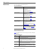
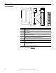
Parts Illustration
For wiring instructions, see Chapter 3.
Item Description
1 Backplane connector—The backplane interface for the ControlLogix system connects the module to
the backplane.
2 Top and bottom guides—Guides provide assistance in seating the removable terminal block (RTB)
onto the module.
3 Connector pins—Input/output, power, and grounding connections are made to the module through
these pins with the use of an RTB.
4 Status indicators—Indicators display the status of communication, module health, and presence of
input/output devices. Use these indicators to help in troubleshooting.
5 Locking tab—The locking tab anchors the RTB on the module and maintains wiring connections.
6 Slots for keying—The slots let you mechanically key the RTB to prevent inadvertently making the
wrong wire connections to your module.
7 Removable terminal block—The RTB lets you connect and house the wiring. The counter module
supports two types of RTBs:
• Cage clamp, catalog number 1756-TBCH
• Spring clamp, catalog number 1756-TBS6H
7
4
5
6
3
2
1
41623