User Manual ControlLogix Low-speed Counter Module Catalog Number 1756-LSC8XIB8I
Important User Information Solid-state equipment has operational characteristics differing from those of electromechanical equipment. Safety Guidelines for the Application, Installation and Maintenance of Solid State Controls (publication SGI-1.1 available from your local Rockwell Automation® sales office or online at http://www.rockwellautomation.com/literature/) describes some important differences between solid-state equipment and hard-wired electromechanical devices.
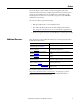
Table of Contents Preface Additional Resources . . . . . . . . . . . . . . . . . . . . . . . . . . . . . . . . . . . . . . . . . . . . . . 5 Chapter 1 Module Features About the Counter Module . . . . . . . . . . . . . . . . . . . . . . . . . . . . . . . . . . . . . . . . 7 Proximity Sensor Compatibility . . . . . . . . . . . . . . . . . . . . . . . . . . . . . . . . . . . . 7 Module Features . . . . . . . . . . . . . . . . . . . . . . . . . . . . . . . . . . . . . . . . . . . . . . . . . .
Table of Contents Chapter 5 Troubleshoot the Module Status Indicators . . . . . . . . . . . . . . . . . . . . . . . . . . . . . . . . . . . . . . . . . . . . . . . . . Software Diagnostics . . . . . . . . . . . . . . . . . . . . . . . . . . . . . . . . . . . . . . . . . . . . . Fault Type Determination . . . . . . . . . . . . . . . . . . . . . . . . . . . . . . . . . . . . Module Error Codes. . . . . . . . . . . . . . . . . . . . . . . . . . . . . . . . . . . . . . . . . . . . . .
Preface The ControlLogix® counter module counts incoming pulses and returns accumulated count, instantaneous and average frequencies, and instantaneous and average pulse width values. The module has two configurable On/Off windows per counter that can be used to affect outputs on a 1756-OB16IEF module in the same chassis. The counter module requires the following: • RSLogix™ 5000 software, version 18.02.00 or later • The Add-on Profile (AOP) for the module available for download at http://support.
Preface Notes: 6 Rockwell Automation Publication 1756-UM536A-EN-P - April 2012
Chapter 1 Module Features About the Counter Module Topic Page About the Counter Module 7 Proximity Sensor Compatibility 7 Module Features 8 Parts Illustration 10 The counter module is an eight counter, eight input point, 24V high-speed DC isolated, sink/source input module. The counter module has eight dedicated, 40 kHz counters. Each counter returns accumulated count, instantaneous frequency, average frequency, instantaneous pulse width, and average pulse width.
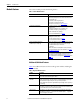
Chapter 1 Module Features Module Features The counter module provides the following features. Table 1 - Counter Module Features Feature Description Dedicated counters Counters 0…7 on the module are dedicated to counting incoming pulses from a proximity sensor. Each counter returns these values: • Accumulated count • Instantaneous and average frequencies • Instantaneous and average pulse width For descriptions of each value, see Table 3 on page 12.
Module Features Chapter 1 Table 2 - Digital I/O Module Features (continued) Feature Description Producer/consumer model Logix5000 controllers let you produce (broadcast) and consume (receive) system-shared tags. The module can produce data without having to be polled first by a controller. The module produces the data, and any owner-controller device or 1756-OB16IEF peer output module can consume it. The module produces count, frequency, and pulse width values at the RPI.
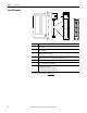
Chapter 1 Module Features Parts Illustration 4 7 5 2 3 6 1 41623 Item Description 1 Backplane connector—The backplane interface for the ControlLogix system connects the module to the backplane. 2 Top and bottom guides—Guides provide assistance in seating the removable terminal block (RTB) onto the module. 3 Connector pins—Input/output, power, and grounding connections are made to the module through these pins with the use of an RTB.
Chapter 2 Module Operation Counters 0…7 Topic Page Counters 0…7 11 Counter Control Functions 15 Output Control 23 Counters 0…7 on the module are dedicated to up and down counting of incoming pulses. The module counts rising pulse edges at a maximum of 40 kHz. However, the following limitations apply as shown in Figure 1: • The duration of a pulse cannot be less than 11 μs, which is the minimum hardware delay time for a transition to be detected by an input.
Chapter 2 Module Operation Each of the eight counters automatically returns the values described in Table 3. Table 3 - Counter Values Value Data Type Description Accumulated count DINT The total number of pulses. The module counts pulses on their rising edge. The module stores accumulated count in the Counter[x].Count input tag. Instantaneous frequency REAL The frequency of the last pulse detected by a counter.
Module Operation Chapter 2 On/Off Windows Each counter has two configurable On/Off windows that compare the accumulated count or frequency of incoming pulses to user-defined On/Off values. When the count or frequency values are within the user-defined window parameters, the module sets the corresponding bit in the Counter[x].InWindow0 or Counter[x].InWindow1 input tag. The module produces data to the system on the rising and falling edge of each On/Off window.
Chapter 2 Module Operation Figure 2 compares two On/Off windows by using the Accumulated Count comparison method. In the first window, the On value is less than the Off value. In the second window, the On value is greater than the Off value. Figure 2 - Window States Based on Accumulated Count On Value > Off Value On Value < Off Value Counter[x].InWindow1 remains Off for 3000 counts. Counter[x].InWindow0 remains On for 3000 counts. Counter[x].InWindow1 turns Off at count 2000. Counter[x].
Module Operation Counter Control Functions Chapter 2 The counter module provides four counter control functions: • Up/Down Count • Count Enable • Reset Count • Preset Count The module provides two methods to invoke counter control functions: • Hardware inputs—You can tie counter control functions to standard hardware inputs 0…7 to let the state of external input devices directly control the functionality of a designated counter.
Chapter 2 Module Operation Up/Down Count Function The Up/Down Count function causes a counter to increment or decrement accumulated count or changes the direction bit for frequency values. To invoke the Up/Down Count function for a counter by using the hardware input method, tie the function to a hardware input on the Input Configuration tab of the Module Properties dialog box as shown in Figure 3.
Module Operation Chapter 2 To invoke the Up/Down Count function by using the output tag method, use the Counter[x]CountDown output tag to define the direction of Counter[x] as shown in Figure 4. By default, the count direction is up. Figure 4 - Counter[x]CountDown Output Tag 0 = Count direction is up, level-sensitive. 1 = Count direction is down, level-sensitive. IMPORTANT The Counter[x].CountDown output tag is active only if the Up/Down Count function is not tied to Counter[x] via a hardware input.
Chapter 2 Module Operation Figure 5 illustrates the input tag values returned when the Up/Down Count function is tied to an input via a hardware input. Figure 5 - Example of Up/Down Count Function 1756-LSC8XIB8I Counter x Counting Sensor Counter Control Hardware Input x Up/Down Control Sensor Count Down Count Up Counting Sensor – + Counter Control Hardware Input Count Total in Counter[x].Count Tag Frequency in Counter[x].Frequency Tag Count Direction in Counter[x].
Module Operation Chapter 2 Count Enable Function The Count Enable function serves as a gate input that controls when counting starts and stops. To invoke the Count Enable function for a counter by using the hardware input method, tie the function to a hardware input on the Input Configuration tab of the Module Properties dialog box as shown in Figure 6 on page 19. Figure 6 - Count Enable Function Controlled by Hardware Input Count Enable function for counter 2 is tied to hardware input 4.
Chapter 2 Module Operation Note that the module continues to calculate frequency and pulse width values even if you disable counting via the Count Enable function. IMPORTANT Either the Count Enable hardware input or the corresponding bit in the Counter[x]DisableCount output tag can determine whether counting is enabled or disabled. Counting is enabled under the following conditions: • Counter[x].
Module Operation Chapter 2 To invoke the Reset Count function by using the output tag method, use the Counter[x].ResetCount output tag as shown in Figure 9. Figure 9 - Counter[x]ResetCount Output Tag 0 = Tag-based reset is not active. 1 = Count transitions to zero on a rising edge. IMPORTANT Either the Reset Count hardware input or the corresponding bit in the Counter[x]ResetCount output tag can determine whether the count is reset.
Chapter 2 Module Operation To invoke the Preset Count function for a counter by using the hardware input method, tie the function to a hardware input on the Input Configuration tab of the Module Properties dialog box as shown in Figure 10. Figure 10 - Preset Count Function Controlled by Hardware Input Preset Count function for counter 4 is tied to hardware input 7.
Module Operation IMPORTANT Output Control Chapter 2 Either the Preset Count hardware input or the corresponding bit in the Counter[x]PresetCount output tag can determine whether the count is preset. The count is preset to the Counter[x].Preset value under the following conditions: • Counter[x].PresetTieToPt configuration tag = 0…7 (rising edge-sensitive) or • Counter[x]PresetCount output tag = 1 (rising edge-sensitive) Inputs from the counter module can affect outputs on a 1756-OB16IEF module.
Chapter 2 Module Operation Notes: 24 Rockwell Automation Publication 1756-UM536A-EN-P - April 2012
Chapter 3 Install the Counter Module Topic Page Install the Module 27 Key the Removable Terminal Block 29 Connect the Wires 30 Wire Terminations 33 Assemble the Removable Terminal Block and Housing 35 Install the Removable Terminal Block 36 Remove the Removable Terminal Block 38 Remove the Module from the Chassis 39 ATTENTION: Environment and Enclosure This equipment is intended for use in a Pollution Degree 2 industrial environment, in overvoltage Category II applications (as defined i
Chapter 3 Install the Counter Module North American Hazardous Location Approval The following information applies when operating this equipment in hazardous locations. Informations sur l’utilisation de cet équipement en environnements dangereux. Products marked "CL I, DIV 2, GP A, B, C, D" are suitable for use in Class I Division 2 Groups A, B, C, D, Hazardous Locations and nonhazardous locations only.
Install the Counter Module Install the Module Chapter 3 You can install or remove the module while chassis power is applied. WARNING: When you insert or remove the module while backplane power is on, an electrical arc can occur. This could cause an explosion in hazardous location installations. Be sure that power is removed or the area is nonhazardous before proceeding. Repeated electrical arcing causes excessive wear to contacts on both the module and its mating connector.
Chapter 3 Install the Counter Module Follow these steps to insert the module into the chassis. 1. Align the circuit board with the top and bottom chassis guides. Top Guide Bottom Guide 20861-M 2. Slide the module into the chassis until the locking tabs click.
Install the Counter Module Key the Removable Terminal Block Chapter 3 Key the removable terminal block (RTB) to prevent inadvertently connecting the wrong wiring in the RTB to your module. Wedge- and U-shaped bands are manually inserted into the RTB and module. This process hinders a wired RTB from being accidentally inserted into a module that does not match the positioning of the respective tabs. Key positions on the module that correspond to unkeyed positions on the RTB.
Chapter 3 Install the Counter Module 3. To key the RTB in positions that correspond to unkeyed module positions, insert the straight, wedge-shaped tab on the RTB with the rounded edge first. Module Side of RTB 0 1 2 34 56 7 20851-M 4. Push the tab onto the RTB until it stops. 5. Repeat step 1…step 4 by using additional U-shaped and straight tabs until the module and RTB lock into each other properly. Connect the Wires Before wiring the module, adhere to these wiring guidelines.
Install the Counter Module Chapter 3 Use an RTB(1) or interface module (IFM) to connect wires to your module. To use an RTB, follow the directions below to connect wires to the RTB. IFMs are prewired prior to shipping. The counter module supports IFM catalog numbers 1492-IFM40F, 1492-IFM40DS24A-4, 1492-IFM40F-FS24A-4, and 1492-IFM40F-FSA-4.
Chapter 3 Install the Counter Module Spring Clamp Follow these steps to wire a spring clamp. 1. Strip 11 mm (7/16 in.) maximum length of wire. 2. Insert the screwdriver into the outer hole of the RTB to depress the springloaded clamp. 3. Insert the wire into the open terminal and remove the screwdriver. Strain Relief Area IMPORTANT 20860-M Make sure the wire, and not the screwdriver, is inserted into the open terminal to prevent damage to the module.
Install the Counter Module Chapter 3 The following diagrams provide wiring examples for the eight counter, eight input point, 24V high-speed DC isolated, sink/source input module. For alternate wiring for use with non-IEC Type 3 sensors, refer to Appendix D.
Chapter 3 Install the Counter Module Figure 13 - Electronic Device Wiring Allen-Bradley Bulletin 872 3-wire DC Proximity Sensor—Normally Open PNP 12…24V DC Black Brown Module Sink Input Wiring 1756-LSC8XIB8I Blue 12…24V DC Return Allen-Bradley Bulletin 872 3-wire DC Proximity Sensor—Normally Open NPN Brown 12…24V DC 12…24V DC Return Blue Black GND-0 GND-1 2 1 IN-0 4 3 IN-1 GND-2 6 5 IN-2 GND-3 8 7 IN-3 GND-4 10 9 IN-4 GND-5 12 11 IN-5 GND-6 14 13 IN-6 GND-7 16 15 IN
Install the Counter Module Assemble the Removable Terminal Block and Housing Chapter 3 Removable housing covers the wired RTB to protect wiring connections when the RTB is seated on the module. Parts of the 1756-TBCH RTB are identified in the table. 1 2 3 2 5 3 4 20858-M Item Description 1 Housing cover 2 Groove 3 Side edge of RTB 4 RTB 5 Strain relief area Follow these steps to attach the RTB to the housing. 1.
Chapter 3 Install the Counter Module Install the Removable Terminal Block This section shows how to install the RTB onto the module to connect the wiring. WARNING: When you connect or disconnect the removable terminal block (RTB) with field side power applied, an electrical arc can occur. This could cause an explosion in hazardous location installations. Be sure that power is removed or the area is nonhazardous before proceeding.
Install the Counter Module Chapter 3 2. Press quickly and evenly to seat the RTB on the module until the latches snap into place. 3. Slide the locking tab down to lock the RTB onto the module.
Chapter 3 Install the Counter Module Remove the Removable Terminal Block If you need to remove the module from the chassis, you must first remove the RTB from the module. 1. Unlock the locking tab at the top of the module. 2. Open the RTB door by using the bottom tab. 3. Hold the spot marked PULL HERE and pull the RTB off the module.
Install the Counter Module Remove the Module from the Chassis Chapter 3 Follow these steps to remove a module from its chassis. 1. Push in the top and bottom locking tabs. 20856-M 2. Pull the module out of the chassis.
Chapter 3 Install the Counter Module Notes: 40 Rockwell Automation Publication 1756-UM536A-EN-P - April 2012
Chapter 4 Configure the Module ControlLogix Overview Topic Page ControlLogix Overview 41 Create a New Module 46 Configure Connection Properties 48 Configure Counters 0…7 50 Configure Hardware Inputs 0…7 53 Download the Configuration 56 Before configuring your module in a local or remote chassis, you must have an understanding of how the module operates with the controller in the ControlLogix system. Every module must be owned by a Logix5000 controller.
Chapter 4 Configure the Module Figure 14 - Module Communication with Owner-controller Logix Controller Counter Module COUNTER ST 01234567 CTR 01234567 O K 3 PEER DEVICE Tags 1 2 Program Logic 4 5 Path No. Description 1 Controller transfers configuration data and commands to the module. 2 External devices generate input signals that are transmitted to the module. 3 Module converts signals, counts incoming pulses, calculates frequency and pulse width values, and then stores the values.
Configure the Module Chapter 4 Direct Connections A direct connection is a real-time data transfer link between the controller and the device that occupies the slot that the configuration data references. When module configuration data is downloaded to an owner-controller, the controller attempts to establish a direct connection to each of the modules referenced by the data.
Chapter 4 Configure the Module IMPORTANT In a peer control operation where the counter module provides peer input data directly to a 1756-OB16IEF module, both the counter module and 1756-OB16IEF module must reside in the same physical chassis. For more information about peer control, refer to the Peer I/O Control Application Technique, publication 1756-AT016. Remote Chassis Operation A remote chassis contains the module but not the module’s owner-controller.
Configure the Module Chapter 4 You must run RSNetWorx software to enable modules in a remote ControlNet chassis. Running RSNetWorx software transfers configuration data to remote modules and establishes a network update time (NUT) for the ControlNet network that is compliant with the desired communication options specified for each module during configuration. If you are not using the modules in a remote ControlNet chassis, running RSNetWorx software is not necessary.
Chapter 4 Configure the Module Create a New Module Before configuring a module, make sure you complete these procedures in RSLogix 5000 software: • Create a controller project. • If you plan to add the module to a remote chassis, add ControlNet or EtherNet/IP communication modules to both the local and remote chassis in the I/O Configuration tree. – For more information on ControlLogix ControlNet modules, see ControlNet Modules in Logix5000 Control Systems, publication CNET-UM001.
Configure the Module Chapter 4 3. On the New Module dialog box, type a name and description for the module and enter the module’s slot number. 4. Click Change. 5. On the Module Definition dialog box, define options for how the module will operate and click OK: • For information about choosing an electronic keying method, see Appendix A. • For information about choosing a connection format, see Connection Formats on page 48. 6. On the New Module dialog box, click OK.
Chapter 4 Configure the Module Connection Formats The initial configuration of a module requires you to choose a connection format. If needed, you can change the connection format when offline after the configuration is downloaded to the controller. Multiple controllers can receive data being produced by a module.
Configure the Module Chapter 4 Follow these steps to configure connection properties. 1. On the Module Properties dialog box, click the Connection tab. 2. Complete the fields as described below and click Apply. Field Description Requested Packet Interval (RPI) Enter an RPI value or use the default value. Inhibit Module Check the checkbox to prevent communication between the owner-controller and the module.
Chapter 4 Configure the Module Configure Counters 0…7 The configuration of counters 0…7 defines the following: • The number of pulses over which to calculate average frequency • The frequency time-out value • Whether the On/Off windows use accumulated count, instantaneous frequency, or average frequency for output control • Window On/Off, preset, and rollover values • Whether to enable filtering for a counter You can configure most of the above values on the Counter Configuration tab of the Module Proper
Configure the Module Chapter 4 3. Complete the fields as described in the table below and click Apply. Field Description Configuration Tag Calculate Average Frequency Over Type the number of pulses to use to calculate average frequency. This value is also used to calculate average pulse width. For more information about how average frequency and average pulse width are calculated, see page 12. Valid values = 0…1, 000 Default = 10 Counter[x].
Chapter 4 Configure the Module 4. Use program logic or the RSLogix 5000 tag editor to define the following values or counter control functions in the module’s output tags. Value or Counter Control Function Output Tag Window On/Off Counter[x].Window0On, Counter[x].Window0Off Counter[x].Window1On, Counter[x].Window1Off Preset Counter[x].Preset Rollover Counter[x].Rollover Count Enable Counter[x].DisableCount Reset Count Counter[x].ResetCount Preset Count Counter[x].
Configure the Module Configure Hardware Inputs 0…7 Chapter 4 You can tie a counter control function for a designated counter to standard hardware inputs 0…7. This enables the state of an external input device to invoke a specific counter function. For more information about counter control functions, refer to Counter Control Functions on page 15. IMPORTANT Each of the counter control functions can also be invoked via the output tags for real-time control.
Chapter 4 Configure the Module 2. In the Hardware Input Ties area, assign counter control functions for individual counters to hardware inputs as described in the table below. IMPORTANT Field A single input can control functionality for multiple counters. For example, you can tie input 3 to the Up/Down Count function for all 8 counters. Only one type of counter control function can be assigned to a single input.
Configure the Module Chapter 4 3. If you enabled filtering for one or more counters on the Counter Configuration tab, configure the filter times under Counter Input Filter Time. Field Description Configuration Tag Off –>On Enter how long an Off to On transition at a counter must remain in the On state before the module counts the transition.
Chapter 4 Configure the Module Download the Configuration After you have changed the configuration for a module, the change does not take effect until you download the new configuration. The software downloads the entire program to the controller and overwrites any existing programs. Follow these steps in RSLogix 5000 software to download a configuration. 1. In the upper-left corner of the RSLogix 5000 window, click the controller status icon and choose Download. 2.
Chapter 5 Troubleshoot the Module Status Indicators Topic Page Status Indicators 57 Software Diagnostics 58 Module Error Codes 60 The module uses the status indicators shown below. COUNTER Standard Hardware Input Status Indicators Counter Input Status Indicators ST 01234567 CTR 01234567 O K OK Status Indicator PEER DEVICE Indicator Status Description OK Status Steady green The module is broadcasting inputs in a normal operating state.
Chapter 5 Troubleshoot the Module Software Diagnostics In addition to the status indicators on the module, RSLogix 5000 software alerts you to fault conditions. The software reports fault conditions in these ways: • A warning icon appears next to the module in the I/O Configuration tree (Figure 16) when the controller-to-module connection is lost.
Troubleshoot the Module Chapter 5 • The Fault tag (Figure 18) shows all 32 bits as set when the connection to the module is lost. Figure 18 - Fault Tag Fault Type Determination When you are monitoring a module’s configuration properties in RSLogix 5000 software and receive a Communication fault message, the Connection tab lists the type of fault in the Module Fault area (Figure 19). For a description of possible faults, see Module Error Codes on page 60.
Chapter 5 Troubleshoot the Module Module Error Codes 60 In RSLogix 5000 software, errors appear in the Module Fault area on the Connection tab of the Module Properties dialog box (Figure 19). The table below lists possible errors. Error Code Description 0x100 Connection in Use—Typically occurs when the module detects a connection attempt, but never receives data resulting in a 60 second timeout. This scenario can be caused by an error with the communication module.
Appendix A Electronic Keying Electronic Keying The electronic keying feature automatically compares the expected module, as shown in the RSLogix 5000 I/O Configuration tree, to the physical module before I/O communication begins. You can use electronic keying to help prevent communication to a module that does not match the type and revision expected. For each module in the I/O Configuration tree, the user-selected keying option determines if, and how, an electronic keying check is performed.
Appendix A Electronic Keying You can find revision information on the General tab of a module’s Properties dialog box. Figure 20 - General Tab IMPORTANT Changing electronic keying selections online may cause the I/O communication connection to the module to be disrupted and may result in a loss of data.
Electronic Keying Appendix A Exact Match keying is also necessary to enable Automatic Firmware Update for the module via the Firmware Supervisor feature from a Logix5000 controller. EXAMPLE In the following scenario, Exact Match keying prevents I/O communication. The module configuration is for a 1756-IB16D module with module revision 3.1. The physical module is a 1756-IB16D module with module revision 3.2.
Appendix A Electronic Keying With Compatible Keying, you can replace a module of a certain Major Revision with one of the same catalog number and the same or later, that is higher, Major Revision. In some cases, the selection makes it possible to use a replacement that is a different catalog number than the original. For example, you can replace a 1756-CNBR module with a 1756-CN2R module. Release notes for individual modules indicate the specific compatibility details.
Electronic Keying Appendix A In the following scenario, Compatible Keying allows I/O communication. The module configuration is for a 1756-IB16D module with module revision 2.1. The physical module is a 1756-IB16D module with module revision 3.2. In this case, communication is allowed because the major revision of the physical module is higher than expected and the module determines that it is compatible with the prior major revision.
Appendix A Electronic Keying If you use Disabled Keying, you must take full responsibility for understanding whether the module being used can fulfill the functional requirements of the application. EXAMPLE In the following scenario, Disable Keying prevents I/O communication. The module configuration is for a 1756-IA16 digital input module. The physical module is a 1756-IF16 analog input module.
Electronic Keying EXAMPLE Appendix A In the following scenario, Disable Keying allows I/O communication. The module configuration is for a 1756-IA16 digital input module. The physical module is a 1756-IB16 digital input module. In this case, communication is allowed because the two digital modules share common data formats. Module Configuration Vendor = Allen-Bradley Product Type = Digital Input Module Catalog Number = 1756-IA16 Major Revision = 2 Minor Revision = 1 Communication is allowed.
Appendix A Electronic Keying Notes: 68 Rockwell Automation Publication 1756-UM536A-EN-P - April 2012
Appendix B Tag Definitions Topic Page Configuration Tags 70 Input Tags 73 Output Tags 74 Module-specific tags and data types are created when you define a module in RSLogix 5000 software. The counter module has three types of tags: • Configuration—Defines the data structure sent from the controller to the module upon powerup. • Output—Defines the data structure continually sent from the controller to the module that can modify the module’s behavior during operation.
Appendix B Tag Definitions Configuration Tags The configuration tags in Table 5 on page 71 define the module’s configuration. IMPORTANT The Counter[x].CountDown output tag is active only if the Up/Down Count function is not tied to Counter[x] via a hardware input. If a hardware input is tied to Counter[x], the hardware input overrides the value of the Counter[x].CountDown output tag.
Tag Definitions Appendix B Table 5 - Counter Module Configuration Tags Name Data Type Definition PtFilterOffOn INT Filter Time Off to On—(Inputs 0…7 only). Defines how long an Off to On input transition must remain in the On state before the module recognizes the transition. Valid filter time = 0…30,000 μs Default = 0 PtFilterOnOff INT Filter Time On to Off—(Inputs 0…7 only). Defines how long an On to Off input transition must remain in the Off state before the module recognizes the transition.
Appendix B Tag Definitions Table 5 - Counter Module Configuration Tags (continued) Name Data Type Definition Counter[x].InvertPreset BOOL Invert Preset Count Function—When set, inverts the hardware input defined in the Counter[x].PresetTieToPt tag, so that Counter[x] is preset only when the input transitions low. 0 = Not inverted. Counter[x] sets the count to the value stored in the Counter[x].Preset output tag when the input transitions high (default). 1 = Inverted.
Tag Definitions Appendix B The input tags in Table 6 indicate the current status of input points. The input module sends this data to the controller or peer output module for processing. Input Tags Table 6 - Counter Module Input Tags Name Data Type Definition Fault DINT Fault—Indicates whether a fault has occurred. The controller sets all 32 bits upon a connection loss. Fault bits 8…15 are also set by these conditions: • Negative values in one or more of the Counter[x].Rollover, Counter[x].
Appendix B Tag Definitions Table 6 - Counter Module Input Tags (continued) Name Data Type Definition Counter[x].InWindow0 BOOL Window 0 Input—Indicates whether the accumulated count or frequency value of Counter[x] is within the parameters defined by the Counter[x].Window0On and Counter[x].Window0Off output tags. A change in window status triggers a Change of State (COS) message to be sent to the owner-controller or peer module. 0 = Counter[x] value is not within window 0.
Tag Definitions IMPORTANT Appendix B Keep in mind the following when using frequency as a window comparison method: • When configured to compare frequency values, window On/Off values are still DINT (32-bit signed integers) while the returned frequency values are REAL (32-bit IEEE float). As a result, the frequency triggers for On/Off windows can only be defined in 1 Hz increments.
Appendix B Tag Definitions Table 7 - Counter Module Output Tags (continued) Name Data Type Definition Counter[x].Window0Off DINT Window 0 Off—Defines the count or frequency value that results in an Off status for window 0. The status for window 0 is stored in the Counter[x].InWindow0 input tag. This tag is used in conjunction with the Counter[x].Window0On tag to create an On/Off window. If the values in the Counter[x].Window0On and Counter[x].Window0Off tags are the same, the window is disabled.
Appendix C Alternate Wiring for Non-IEC Type 3 Sensors Topic Page Module Input Circuit 77 Input Specifications 77 Choose a Pull-up Resistor for an Open Collector Sensor 78 Open Collector Wiring without a Resistor 78 The following sections provide recommendations on how to use your counter module with an open collector sensor that is not IEC compliant. Refer to the input circuit shown below to wire a counter module to an open collector sensor that requires an external pull-up resistor.
Appendix C Alternate Wiring for Non-IEC Type 3 Sensors Choose a Pull-up Resistor for an Open Collector Sensor To choose a pull-up resistor for an open collector sensor, use the module’s nominal input current specifications in Table 8 and the transistor’s current rating to calculate the voltage drop across the pull-up resistor when the transistor is Off and On: – Choose a pull-up resistor that provides a minimum of 10V at the module terminals when the transistor is Off (input module is On).
Index Numerics 1756-OB16IEF module 7, 8, 14, 23, 44, 45 1756-TBCH cage clamp 31 1756-TBE extended-depth housing 32 1756-TBS6H spring clamp 31 A accumulated count 12 alternate wiring 77 assemble removable terminal block 35 average frequency 12 average pulse width 12 C cage clamp 31 calculation average frequency 12, 51 average pulse width 12, 73 timeout 51 change of state 9, 23, 74 chassis data transfer 44 local 43 module insertion 28 module removal 38-39 peer control requirements 44, 45 power hazard 27 rem
Index E edge sensitive 20, 22 electronic device wiring 34 electronic keying 61 electrostatic discharge 27 enable count function 19, 75 filter 55 error code 60 exact match keying 62 F fault reporting 8, 58, 59 features, module 8 filter about 8 configuration tags 71 configure 55 disable 55 enable 51, 55 firmware revision 5 format, connection 48 frequency average 12 instantaneous 12 sequence 73 timeout 72 function Count Enable 19 counter control 15 Preset Count 21 Reset Count 20 Up/Down Count 16-18 input, c
Index O On/Off window 13 open collector sensor IEC compliant 7 non-IEC compliant 77 output control 23 output tags 15, 74 P peer connection 23 peer control 5, 14, 23, 44, 45 Preset Count function 21 preset value 21 producer/consumer model 9 properties connection 48 module 48-55 proximity sensor compatibility 7 pull-up resistor 78 pulse cycle limit 11 pulse width 12 average 12 instantaneous 12 sequence 73 R remote chassis operation 43, 44 removable terminal block assemble 35 catalog numbers 31 connect wire
Index Notes: 82 Rockwell Automation Publication 1756-UM536A-EN-P - April 2012
Rockwell Automation Support Rockwell Automation provides technical information on the Web to assist you in using its products. At http://www.rockwellautomation.com/support, you can find technical manuals, technical and application notes, sample code and links to software service packs, and a MySupport feature that you can customize to make the best use of these tools. You can also visit our Knowledgebase at http://www.rockwellautomation.