Installation Instructions Original Instructions Armor GuardLogix Controller Catalog Numbers 1756-L72EROMS Topic Page Important User Information 2 About the Armor GuardLogix Controller 3 Prevent Electrostatic Discharge 3 Before You Begin 4 Install the Armor GuardLogix Controller 6 Mount the Controller 6 Ground the Controller 8 Open the Access Door 8 Remove and Install the SD Card 8 Connect to the USB Port 9 Make Network Connections 10 Make Power Connections 11 Set the Network IP Ad
Armor GuardLogix Controller Important User Information Read this document and the documents listed in the additional resources section about installation, configuration, and operation of this equipment before you install, configure, operate, or maintain this product. Users are required to familiarize themselves with installation and wiring instructions in addition to requirements of all applicable codes, laws, and standards.
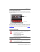
Armor GuardLogix Controller 3 About the Armor GuardLogix Controller The Armor™ GuardLogix® controller combines a 1756-L72S GuardLogix controller and safety partner with two Ethernet/IP DLR-capable communication channels in an IP67-rated housing for mounting on a machine.
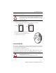
Armor GuardLogix Controller Environment and Enclosure ATTENTION: This equipment is intended for use in overvoltage Category II applications (as defined in IEC 60664-1), at altitudes up to 2000 m (6562 ft) without derating. This equipment is not intended for use in residential environments and may not provide adequate protection to radio communication services in such environments. This equipment is supplied as enclosed equipment.
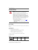
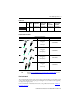
Armor GuardLogix Controller 5 Patchcords (1) No. of Pins Assembly Rating Straight Female Straight Male Straight Female, Right Angle Male Right Angle Female, Straight Male Right Angle Female, Right Angle Male 4 600V, 10 A 889N-F4AFNM-(1) 889N-F4AFNE-(1) 889N-R4AFNM-(1) 889N-R4AFNE-(1) Replace (1) with 1 (1 m), 2 (2 m), 5 (5 m), and 10 (10 m) for standard cable lengths. Industrial Ethernet Media Patchcords and Cordsets IP67 M12 D Code (1) Connector Type Cat. No.
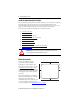
Armor GuardLogix Controller Install the Armor GuardLogix Controller The controller ships with the power switch inside the enclosure set to ON and the controller in Remote Program mode. You can make power connections and EtherNet/IP network connections without opening the access door on the enclosure. However, if you need to access the power switch, USB port, or SD card, you will need to open the enclosure door. Follow these steps, described in this publication, to install the controller. 1.
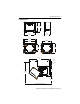
Armor GuardLogix Controller 7 Product Dimensions 240 mm 265 mm (9.4 in.) (10.4 in.) 165mm (6.5 in.) 292 mm (11.5 in. ) 327 mm (12.9 in.) 215 mm (8.5 in.) 298 mm (11.7 in.) 172 mm (6.8 in.) Mounting feet in horizontal orientation 225.75 mm 8.9 in. 245 mm (10 in.) Mounting feet in vertical orientation 550 mm 21.7 in. 32.25 mm 1.3 in. 86.55 mm 3.4 in. 265 mm 10 in. 550 mm 21.7 in. 198.9 mm 7.8 in.
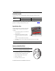
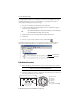
Armor GuardLogix Controller Ground the Controller You must provide a proper grounding path by using the ground lug on the bottom of the enclosure. Wire Size PE Ground 1.3…5.2 mm Tightening Torque 2 (#16…#10 AWG) 2 N•m (17.7 in-lb) Refer to Industrial Automation Wiring and Grounding Guidelines, publication 1770-4.1 for guidelines on installing an industrial control system.
Armor GuardLogix Controller 9 Follow these steps to install the SD card. ATTENTION: If you are not sure of the contents of the memory card, before you install the card, turn the keyswitch of the controller to the PROG position. Depending on the contents of the card, a power cycle or fault could cause the card to load a different project or operating system into the controller. 1. Open the access door on the enclosure. 2. Verify that the SD card is locked or unlocked according to your preference.
Armor GuardLogix Controller To configure RSLinx software to use a USB port, you need to set up a USB driver. To set up a USB driver, follow these steps. If you are using Windows 7 operating system, the driver is automatically installed and you can proceed to step 5. 1. Connect your controller and workstation by using a USB cable. 2. On the Found New Hardware Wizard dialog box, click one of the Windows Update connection options and click Next.
Armor GuardLogix Controller 11 IMPORTANT Use the 1585D–M4DC–H: Polyamide small body unshielded or the 1585D–M4DC–SH: Zinc die-cast large body shielded mating connectors for the D-Code M12 female network connector. IMPORTANT Use two twisted-pair CAT5E UTP or STP cable.
Armor GuardLogix Controller Set the Network IP Address of the EtherNet/IP Modules The EtherNet/IP communication modules reside in slots 2 and 3 of the ControlLogix chassis within the enclosure. The modules are shipped with Bootstrap Protocol (BOOTP)/Dynamic Host Configuration Protocol (DHCP) enabled and their rotary switches set to 999. You can use the following methods to set the IP address of each module.
Armor GuardLogix Controller 13 3. Type the Subnet Mask of the network. The Gateway address, Primary and/or Secondary DNS address, and Domain Name fields are optional. 4. Click OK. The Request History panel shows the hardware addresses of all modules issuing BOOTP requests. 5. Select the appropriate module and click Add to Relation List. 6. On the New Entry dialog box, type an IP Address, Hostname, and Description for the module. 7. Click OK. 8.
Armor GuardLogix Controller 9. Click Disable BOOTP/DHCP. IMPORTANT If you do not click Disable BOOTP/DHCP, the host controller clears the current IP configuration and begins sending BOOTP requests again each time power is cycled. Use RSLinx or the Logix Designer Application This table describes when to set the network IP address with RSLinx software or the Logix Designer application. Conditions Use Page A BOOTP server is not available.
Armor GuardLogix Controller 15 4. On the Module Configuration dialog box, click the Port Configuration tab. 5. For Network Configuration Type, click Static to permanently assign this configuration to the port . IMPORTANT If you click Dynamic, on a power cycle, the controller clears the current IP configuration and resumes sending BOOTP requests. 6. Type the IP address in the IP Address field and add fill in additional fields, if needed. 7. Configure the port settings.
Armor GuardLogix Controller Set the Network IP Address with the Logix Designer application Follow these steps to use the Logix Designer application to set the module’s IP address. 1. In the Controller Organizer, right-click the EtherNet/IP module and choose Properties. 2. On the Module Properties dialog box, click the Port Configuration tab. 3. In the IP Address field, type the IP address. 4. In the other fields, type the other network parameters, if needed.
Armor GuardLogix Controller 17 Update the Controller The controller ships without firmware. Controller firmware is packaged with the Studio 5000 environment. In addition, controller firmware is also available for download from the Rockwell Automation Technical Support website at: http://www.rockwellautomation.com/support/. You can upgrade your firmware by using either ControlFLASH™ software or by using the AutoFlash feature of the Logix Designer application.
Armor GuardLogix Controller Use AutoFlash to Update Firmware To update your controller firmware with the AutoFlash feature, follow these steps. 1. Verify that the appropriate network connection is made and your network driver is configured in RSLinx software. 2. Use the Logix Designer application to create a controller project at the version you need. 3. Click RSWho to specify the controller path. 4. Select your controller and click Update Firmware. 5. Select the firmware revision you want. 6.
Armor GuardLogix Controller 19 Primary Controller Status Indicator Descriptions Indicator Status Description SD Off No activity is occurring with the memory card. Green, Flashing The controller is reading from or writing to the memory card. Do not remove the memory card while the controller is reading or writing. Green OK Red, Flashing The memory card does not have a valid file system. Red The memory card is not recognized by the controller. Off No power is applied.
Armor GuardLogix Controller EtherNet/IP Module Status Indicators The EtherNet/IP communication modules support these status indicators. Indicator Status Description Off One of these conditions exists: • The module is not powered. – Verify there is chassis power. – Verify that the module is completely inserted into the chassis and backplane. – Make sure the module has been configured. • No link exists on the port. • The port is administratively disabled (LNK2).
Armor GuardLogix Controller 21 not corrupt, or preform the procedure prior to downloading any project to your Armor GuardLogix controller. IMPORTANT To avoid inadvertently over-writing your application program, you must not use the 1784-SD1 memory card that shipped installed in the Armor GuardLogix controller. Follow these steps to create the recovery memory card. 1. Update the Armor GuardLogix controller to the desired firmware revision by following the instructions in Update the Controller on page 17.
Armor GuardLogix Controller Specifications This section lists general specifications specific to the enclosure. Specifications for the components in the Armor GuardLogix controller enclosure are in their respective Technical Data publications, listed in the Additional Resources on page 23.
Armor GuardLogix Controller 23 Additional Resources These documents contain additional information concerning related products from Rockwell Automation. Resource Safety Controllers EtherNet/IP Networks Specifications for Armor GuardLogix Components Description GuardLogix 5570 Controllers User Manual, publication 1756-UM022 Provides information on how to install, configure, program, and use GuardLogix 5570 controllers in Studio 5000 Logix Designer projects.
Rockwell Automation Support Rockwell Automation provides technical information on the Web to assist you in using its products. At http://www.rockwellautomation.com/support you can find technical and application notes, sample code, and links to software service packs. You can also visit our Support Center at https://rockwellautomation.custhelp.com/ for software updates, support chats and forums, technical information, FAQs, and to sign up for product notification updates.