ControlLogix Sequence of Events Module 1756-IB16ISOE (24/48V dc), 1756-IH16ISOE (125V dc) User Manual
Important User Information Solid state equipment has operational characteristics differing from those of electromechanical equipment. Safety Guidelines for the Application, Installation and Maintenance of Solid State Controls (Publication SGI-1.1 available from your local Rockwell Automation sales office or online at http://www.ab.com/manuals/gi) describes some important differences between solid state equipment and hard-wired electromechanical devices.
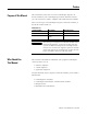
Preface Purpose of This Manual This manual describes how to use the ControlLogix Sequence of Events module in your ControlLogix application. With this manual, you can learn how to install, configure and troubleshoot the module. There are two types of ControlLogix Sequence of Events modules, as described in Table Preface.1: Table Preface.
Preface 2 What This Manual Contains Table Preface.2 lists the sections contained in this manual: Table Preface.
Preface Preventing Electrostatic Discharge 3 This module is sensitive to electrostatic discharge. ATTENTION This equipment is sensitive to electrostatic discharge, which can cause internal damage and affect normal operation. Follow these guidelines when you handle this equipment: • Touch a grounded object to discharge potential static. • Wear an approved grounding wriststrap. • Do not touch connectors or pins on component boards. • Do not touch circuit components inside the equipment.
Preface 4 Environment and Enclosure ATTENTION This equipment is intended for use in a Pollution Degree 2 industrial environment, in overvoltage Category II applications (as defined in IEC publication 60664-1), at altitudes up to 2000 meters without derating. This equipment is considered Group 1, Class A industrial equipment according to IEC/CISPR Publication 11.
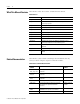
Table of Contents Chapter 1 What is the ControlLogix Sequence of Events Module? What This Chapter Contains . . . . . . . . . . . . . . . . . . . . . . . What does Sequence of Events Module Do? . . . . . . . . . . . . Timestamping Using the Coordinated System Time (CST) On-Board Data Storage . . . . . . . . . . . . . . . . . . . . . . . . Two Modes of Operation . . . . . . . . . . . . . . . . . . . . . . . What Else Does the Sequence of Event Module Do? . . . . . .
Table of Contents 2 Chapter 4 Configuring the Sequence of Events Module What This Chapter Contains . . . . . . . . . . . . . . . . . . Configuring Your I/O Module . . . . . . . . . . . . . . . . . RSLogix 5000 Configuration Software . . . . . . . . . Overview of the Configuration Process . . . . . . . . . . Adding a New Module to Your RSLogix 5000 Project Communications Format. . . . . . . . . . . . . . . . . . . Electronic Keying. . . . . . . . . . . . . . . . . . . . . . . .
Table of Contents 3 Chapter 6 Using The Sequence of Events Module in CST Per Point Mode What This Chapter Contains . . . . . . . . . . . . . . . . . . . . . . Overview of the Mode . . . . . . . . . . . . . . . . . . . . . . . . . . How Does the Module Store Timestamp Data in CST Per Point Mode? . . . . . . . . . . . . . . . . . . . . . . . . . . . . . . . What Are The Typical Applications Where CST Per Point Mode is Used?. . . . . . . . . . . . . . . . . . . . . . . . . . . . . . . . .
Table of Contents 4 Chapter 8 Troubleshooting the Sequence of Events Module What This Chapter Contains . . . . . . . . . . . . . . . . Using LED Status Indicators . . . . . . . . . . . . . . . . . Using RSLogix 5000 To Troubleshoot the Module . Determining Fault Type . . . . . . . . . . . . . . . . . Chapter Summary and What’s Next . . . . . . . . . . . . . . . . . . . . . . . . . . . . . . . . . . . . . . . . . . . . . . 8-1 8-1 8-2 8-4 8-4 . . . . . . . . . . . . . . . . . . . . . . . .
Chapter 1 What is the ControlLogix Sequence of Events Module? What This Chapter Contains This chapter describes the ControlLogix Sequence of Events module. Table 1.
1-2 What is the ControlLogix Sequence of Events Module? CST cannot easily translate to real-time but serves as a relative time reference. Each module in a chassis has access to this reference. The Sequence of Events module grabs the current CST value at the time of the input state change to timestamp the input data. You can propagate the same CST value across multiple chassis, effectively making sure that modules in separate chassis use the same time reference in all their operations, if necessary.
What is the ControlLogix Sequence of Events Module? 1-3 Two Modes of Operation The Sequence of Events module can operate in either of the modes described in Table 1.2: Table 1.2 Operational mode: Description: CST Per Point Mode The module timestamps up to 2 input transitions per input, one for OFF to ON transitions and another for ON to OFF transitions. First In First Out (FIFO) Mode The module timestamps an unlimited number of input transitions, regardless of direction (i.e.
1-4 What is the ControlLogix Sequence of Events Module? Understanding the Module’s Physical Features ControlLogix modules mount in a ControlLogix chassis and use a Removable Terminal Block (RTB), or a Bulletin 1492 Interface Module cable that connects to an IFM, to connect all field-side wiring. Before you use your module, you should have already: • installed and grounded a 1756 chassis and power supply. To install these products, refer to the publications listed in Table Preface.3 on page Preface-2.
What is the ControlLogix Sequence of Events Module? Using Module Identification and Status Information 1-5 Each Sequence of Events module maintains specific identification information that separates it from all other modules. This information assists you in tracking all the components of your system. For example, you can track module identification information to be aware of exactly what modules are located in any ControlLogix chassis at any time.
1-6 What is the ControlLogix Sequence of Events Module? Chapter Summary and What’s Next Publication 1756-UM528A-EN-P - April 2004 In this chapter you read about what the ControlLogix Sequence of Events module is.
Chapter 2 How Does the Sequence of Events Module Operate in a ControlLogix System? What This Chapter Contains This chapter describes how the Sequence of Events module operates in a ControlLogix system. Table 2.
2-2 How Does the Sequence of Events Module Operate in a ControlLogix System? Similar Functionality to Standard ControlLogix DC Input Modules With respect to general module operation in a ControlLogix system, the Sequence of Events module operates similarly to other ControlLogix digital input modules in many ways. This chapter focuses on how the Sequence of Events module’s behavior differs from that of other ControlLogix digital input modules.
How Does the Sequence of Events Module Operate in a ControlLogix System? 2-3 Table 2.3 Ways that a Sequence of Events Module Behave Like Other ControlLogix Digital Input Modules Concept: Description: Making Connections ControlLogix controllers can make direct or rack connections to digital I/O modules. The controller can only make a direct connection to the Sequence of Events module. The controller cannot make rack connections to the Sequence of Events module.
2-4 How Does the Sequence of Events Module Operate in a ControlLogix System? Propagating a Signal From Field Device to Backplane As shown in Figure 2.1, the Sequence of Events module receives a signal at the RTB and processes it internally before sending a signal to the ControlLogix backplane via the Requested Packet Interval (RPI) or at na Enable CST Capture occurrence.
How Does the Sequence of Events Module Operate in a ControlLogix System? 2-5 Figure 2.
2-6 How Does the Sequence of Events Module Operate in a ControlLogix System? Sequence of Events Module in a Local Chassis When a Sequence of Events module resides in the local chassis (i.e., the same chassis as the owner-controller), the following two configuration parameters affect how and when an input module multicasts data: • Requested Packet Interval (RPI) • Enable CST Capture Requested Packet Interval (RPI) This interval specifies the rate at which a module multicasts its data to the controller.
How Does the Sequence of Events Module Operate in a ControlLogix System? 2-7 When Enable CST Capture is enabled for specific points and transitions occur for those points, the Sequence of Events module not only captures the CST at the transition occurrence but also sends input data to the controller. Because the RPI and Enable CST Capture functions are asynchronous to the program scan, it is possible for an input to change state during program scan execution. The point must be “buffered” to prevent this.
2-8 How Does the Sequence of Events Module Operate in a ControlLogix System? Sequence of Events Module in a Remote Chassis If your Sequence of Events module physically resides in a chassis other than where the owner-controller is (e.g. a remote chassis connected via ControlNet), the role of the RPI and the module’s Enable CST Capture behavior changes slightly with respect to getting data to the owner-controller.
How Does the Sequence of Events Module Operate in a ControlLogix System? 2-9 The “reserved” spot on the network and the module’s RPI are asynchronous to each other. This means there are Best and Worst Case scenarios as to when the owner-controller will receive updated channel data from the module in a remote chassis. Best Case RPI Multicast Scenario In the Best Case scenario, the module performs an RPI multicast with updated channel data just before the “reserved” network slot is made available.
2-10 How Does the Sequence of Events Module Operate in a ControlLogix System? When selecting values for the remotely located module’s RPI, system throughput is optimized when its RPI value is a power of 2 times the current NUT running on ControlNet. For example, Table 2.5 shows recommended RPI values for a system using a NUT of 5mS: Table 2.
Chapter 3 Installing the Sequence of Events Module What This Chapter Contains This chapter describes how to install the Sequence of Events module. Table 3.
3-2 Installing the Sequence of Events Module 1. Align circuit board with top and bottom chassis guides. Figure 3.1 Printed Circuit Board 20861-M 2. Slide module into chassis until module tabs ‘click’. Figure 3.
Installing the Sequence of Events Module Keying the Removable Terminal Block 3-3 Key the RTB to prevent inadvertently connecting the incorrect RTB to your module. When the RTB mounts onto the module, keying positions match up. For example, if you place a U-shaped keying band in position #4 on the module, you cannot place a wedge-shaped tab in #4 on the RTB or your RTB does not mount on the module. We recommend that you use a unique keying pattern for each slot in the chassis. 1.
3-4 Installing the Sequence of Events Module Connecting Wiring You can use an RTB or a Bulletin 1492 prewired Interface Module (IFM) to connect wiring to your module. You must connect wires to the RTB. An IFM has been prewired before you received it. If you are using an IFM to connect wiring to the module, skip this section and go to page 3-7. Wiring the RTB You can use either of the following RTBs with your Sequence of Events module.
Installing the Sequence of Events Module 3-5 Spring Clamp RTB 1. Strip 7/16 inch (11mm) maximum length of wire. 2. Insert the screwdriver into the inner hole of the RTB. 3. Insert the wire into the open terminal and remove the screwdriver. Figure 3.6 Strain relief area 20860-M Recommendations for Wiring Your RTB Consider the following guidelines when wiring your RTB: • Begin wiring the RTB at the bottom terminals and move up. • Use a tie to secure the wires in the strain relief area of the RTB.
3-6 Installing the Sequence of Events Module Wiring the Sequence of Events Module Use Figure 3.7 to wire your Sequence of Events module. WARNING If you connect or disconnect wiring while the field-side power is on, an electrical arc can occur. This could cause an explosion in hazardous location installations. Be sure that power is removed or the area is nonhazardous before proceeding. Figure 3.
Installing the Sequence of Events Module Assembling The Removable Terminal Block and the Housing 3-7 Removable housing covers the wired RTB to protect wiring connections when the RTB is seated on the module. 1. Align the grooves at the bottom of each side of the housing with the side edges of the RTB. Figure 3.8 Housing Groove Side edge of RTB Groove Strain relief area Side edge of RTB RTB 20858-M 1756-TBCH RTB shown for reference 2. Slide the RTB into the housing until it snaps into place.
3-8 Installing the Sequence of Events Module Choosing the Extended-Depth Housing There are two housing options you must consider when wiring your Sequence of Events module–standard-depth or extended-depth. When you order an RTB for your module, you receive a standard-depth housing with the RTB. If your application uses heavy gauge wiring, you can order an extended-depth housing. This housing does not come with an RTB. You can use one of the housings listed in Table 3.2. Table 3.
Installing the Sequence of Events Module 3-9 Recommendations for Using the Extended-Depth Housing Consider the following recommendations when deciding to use an extended-depth housing on your Sequence of Events module. It is recommended you use the 1756-TBE when: • using >36 18AWG wires • using >23 14AWG wires Cabinet Size Considerations With the Extended-Depth Housing When you use an extended-depth housing (1756-TBE), the module depth is increased.
3-10 Installing the Sequence of Events Module Installing the Removable Terminal Block Install the RTB onto the module to connect wiring. ATTENTION Shock hazard exists. If the RTB is installed onto the module while the field-side power is applied, the RTB will be electrically live. Do not touch the RTB’s terminals. Failure to observe this caution may cause personal injury. The RTB is designed to support Removal and Insertion Under Power (RIUP).
Installing the Sequence of Events Module 3-11 2. Press quickly and evenly to seat the RTB on the module until the latches snap into place. Locking tab 20854-M 3. Slide the locking tab down to lock the RTB onto the module.
3-12 Installing the Sequence of Events Module Removing the Removable Terminal Block If you need to remove the module from the chassis, you must first remove the RTB from the module. ATTENTION Shock hazard exists. If the RTB is removed from the module while the field-side power is applied, the module will be electrically live. Do not touch the RTB’s terminals. Failure to observe this caution may cause personal injury. The RTB is designed to support Removal and Insertion Under Power (RIUP).
Installing the Sequence of Events Module Removing the Module from the Chassis 3-13 1. Push in the top and bottom locking tabs. Locking tabs 20856-M 2. Pull module out of the chassis.
3-14 Installing the Sequence of Events Module Chapter Summary and What’s Next In this chapter, you read about: • • • • • • • installing the module. keying the RTB and IFM. connecting wiring. assembling the RTB and the housing. installing the RTB or IFM onto the module. removing the RTB from the module. removing the module from the chassis. Chapter 4 explains Configuring the Sequence of Events Module.
Chapter 4 Configuring the Sequence of Events Module What This Chapter Contains This chapter describes how to configure your Sequence of Events module. Table 4.
4-2 Configuring the Sequence of Events Module Overview of the Configuration Process When you use the RSLogix 5000 software to configure a Sequence of Events module, you must perform the following steps: 1. Add the new module to your RSLogix 5000 project. 2. Accept the default configuration or change it to specific configuration for the module. 3. Edit configuration for a module when changes are needed. Figure 4.1 shows an overview of the configuration process. Figure 4.
Configuring the Sequence of Events Module Adding a New Module to Your RSLogix 5000 Project 4-3 After you have started RSLogix 5000 and created a controller, you must add a new module to your project. The wizard allows you to create a new module and write configuration. You can use default configuration or write specific configuration for your application. IMPORTANT You must be offline when you create a new module. 1. If necessary, go offline.
4-4 Configuring the Sequence of Events Module 3. When the Select Module Type screen appears, select the Sequence of Events module. A. Select the Sequence of Events module. B. Click OK. 4. Configure the module. The first screen of the configuration wizard is shown below. A. Name the module. B. Select the module’s slot number. C. Choose a Communications Format. For more information, see page 4-5. D. Make sure the Minor Revision number matches your module’s minor revision. E.
Configuring the Sequence of Events Module 4-5 Communications Format The communications format determines what operational mode your Sequence of Events module uses and, consequently, what tags RSLogix 5000 generates when configuration is complete. Once a module is created, you cannot change the communications format unless you delete and recreate the module. Table 4.2 lists the communications formats used with input modules: Table 4.
4-6 Configuring the Sequence of Events Module Using the Default Configuration If you use the default configuration and click on Finish, you are done. Altering the Default Configuration If you click Next in step 4 on page 4-4, you can write specific configuration for your module in RSLogix 5000. Some of the screens that appear during this initial module configuration process are blank and are not shown here. However, those screens can be important during online monitoring.
Configuring the Sequence of Events Module Downloading Configuration 4-7 After you write configuration for your Sequence of Events module, the module does not use this configuration until you download it to the owner-controller. The download transfers the entire program to the controller, overwriting any existing program. Download module configuration as shown below. A. Click here to see the pull-down menu. B. Click download.
4-8 Configuring the Sequence of Events Module The editing process begins on the main page of RSLogix 5000. A. Right-click on the module. B. Select Properties The General tab of the configuration wizard appears. Click on the tab of the page that you want to view or reconfigure and make any appropriate changes. Make any necessary changes as shown in the example below. A. Click the tab where you need to reconfigure the module. In this example, CST Capture was disabled for several input points. B.
Configuring the Sequence of Events Module Configuring Modules in a Remote Chassis 4-9 ControlLogix ControlNet Interface modules (1756-CNB or 1756-CNBR) or the EtherNet/IP Bridge module (1756-ENBT) are required to communicate with Sequence of Events modules in a remote chassis. You must configure the communications module in the local chassis and the remote chassis before adding remote Sequence of Events modules to your project. 1. Add a communications module to the local chassis. A.
4-10 Configuring the Sequence of Events Module 4. Add a communications module to the remote chassis. A. Right-click on the local communication module. B. Select New Module 5. Select a communications module for the remote chassis. 6. Configure the communications module in the remote chassis. 7. Add a Sequence of Events module to the remote chassis. A. Right-click on the remote communication module. B. Select New Module 8. Configure the new Sequence of Events module as described earlier in this chapter.
Configuring the Sequence of Events Module Chapter Summary and What’s Next 4-11 In this chapter, you read about configuring your Sequence of Events module. Chapter 5 describes Using the Sequence of Events Module Features.
4-12 Configuring the Sequence of Events Module Notes: Publication 1756-UM528A-EN-P - April 2004
Chapter 5 Using the Sequence of Events Module Features What This Chapter Contains This chapter describes the features available on the Sequence of Events module. Table 5.
5-2 Using the Sequence of Events Module Features Determining Module Compatibility Primarily, a Sequence of Events module is used to timestamp input data. However, additionally, the module interfaces to sensing devices and detects whether they are ON or OFF. The module also converts ON/OFF signals from user devices to appropriate logic level for use in the processor.
Using the Sequence of Events Module Features Module Features That Can Be Configured 5-3 Table 5.2 lists features on the Sequence of Events module that can be configured. Table 5.2 This feature: is described on: Two Operational Modes 5-3 Enable CST Capture 5-5 Chatter Detection 5-8 Software Configurable Input Filters 5-10 Latch CST 5-7 Electronic Keying 5-13 Module Inhibiting 5-15 Two Operational Modes The Sequence of Events module can operate in either of the modes described in Table 5.
5-4 Using the Sequence of Events Module Features During initial module configuration, you must choose a communication format for the module. The communication format determines the mode in which your module operates. The example screen below shows how to choose your module’s communication format and, thus, operational mode. Use this pull-down menu to choose a communication format.
Using the Sequence of Events Module Features 5-5 Enable CST Capture Enable CST Capture instructs the Sequence of Events module to timestamp specific input points transitions.
5-6 Using the Sequence of Events Module Features Use the Configuration tab in RSLogix 5000 to set Enable CST Capture, as shown in the example below. Click the Configuration tab. • Click on the individual boxes for each input point to enable CST Capture for that point. • Clear the individual boxes for each input point to disable CST Capture for that point. You can also use these boxes to enable or disable all points simultaneously. IMPORTANT The basic function of Enable CST Capture (i.e.
Using the Sequence of Events Module Features 5-7 Latch CST Latch CST can be used to prevent the Sequence of Events module from overwriting input data once it is timestamped. • If Latch CST is enabled, the module only timestamps a specific number of input transitions(e.g., the first transition in CST Per Point mode) and ignores future input transitions (at least until the controller clears the timestamp data already received, as described on page 6-12 and page 7-20).
5-8 Using the Sequence of Events Module Features Chatter Detection To detect a faulty input device wired to the Sequence of Events module, the module can use Chatter Detection to detect a chattering signal from a device connected to one of its inputs (e.g., rapid transitions from a failed contact) and ignore the data. If not accounted for, chatter can cause the module to timestamp invalid input transitions.
Using the Sequence of Events Module Features 5-9 Use the Configuration tab in RSLogix 5000 to configure Chatter Detection, as shown in the example below. A. Type the number of events. Range is 2-127 events. Use 0 to disable this feature. B. Type the time (measured in milliseconds). You can use up to 10,000 milliseconds. In this example, if 5 events occur on input point 0 within any 20ms time frame, the module considers the point to be chattering.
5-10 Using the Sequence of Events Module Features Software Configurable Input Filters To account for hard contact “bounce”, you can configure ON to OFF and OFF to ON input filter times in RSLogix 5000 for your Sequence of Events module. These filters define how long an input transition must remain in the new state before the module considers the transition valid. IMPORTANT Input filters are applied to all inputs on the Sequence of Events module.
Using the Sequence of Events Module Features 5-11 In the example, a Sequence of Events module: • is Enable CST Capture-enabled for all of its points • uses a 2ms input filter setting for OFF to ON transitions Three possible scenarios can result after an input transitioning from OFF to ON in the given circumstances. • Scenario #1 (no bounce) – The input turns ON and remains for the full 2ms.
5-12 Using the Sequence of Events Module Features • Scenario #3 – The input turns ON but turns OFF before 2ms (length of the input filter setting) elapses. In this case, the Sequence of Events module continues to scan the input every 25µs for 4x the length of the input filter setting (i.e., for 8ms). In those 8ms, the input never remains ON for at least 2ms (i.e., the input filter setting). In this case, the module considers the transition invalid and drops the data timestamped at the original transition.
Using the Sequence of Events Module Features 5-13 Electronic Keying Instead of plastic mechanical backplane keys, electronic keying allows the ControlLogix system to control what modules belong in the various slots of a configured system. During module configuration, you must choose one of the following keying options for your Sequence of Events module: • Exact Match • Compatible Module • Disable Keying When the controller attempts to connect to and configure a Sequence of Events module (e.g.
5-14 Using the Sequence of Events Module Features Table 5.4 describes the keying options available with your module. Table 5.4 Keying option: Definition: Exact Match All of the parameters listed above must match or the inserted module will reject a connection to the controller. Compatible Module The Compatible Match mode allows a Sequence of Events module to determine whether it can emulate the module defined in the configuration sent from the controller.
Using the Sequence of Events Module Features 5-15 Module Inhibiting With module inhibiting, you can indefinitely suspend a connection between an owner-controller and a Sequence of Events module. This process can occur in the following way: • You write configuration for a Sequence of Events module but inhibit the module to prevent it from communicating with the owner-controller.
5-16 Using the Sequence of Events Module Features Other Inherent Module Features Table 5.5 lists features on the Sequence of Events module that cannot be configured. Table 5.
Using the Sequence of Events Module Features 5-17 Fully Software Configurable RSLogix 5000 uses a custom, easily understood interface to write configuration. All module features are enabled or disabled through the I/O configuration portion of the software. You can also use the software to interrogate your Sequence of Events module to retrieve: • • • • • • serial number revision information product code vendor identification error/fault information diagnostic counters.
5-18 Using the Sequence of Events Module Features Status Indicator Information Each Sequence of Events module has LED status indicators on the front of the module that allows you to check the module health and operational status. Table 5.6 describes the module’s LED status indicators: Table 5.6 Status: Description: I/O status This yellow display indicates the ON/OFF state of the field device. (ST LEDs) Module status This red/green display indicates the module’s communication/module health status.
Using the Sequence of Events Module Features 5-19 Full Class I Division 2 Compliance The Sequence of Events module maintains CSA Class I Division 2 system certification. This allows the ControlLogix system to be placed in an environment other than only a 100% hazard free. IMPORTANT Modules should not be pulled under power, nor should a powered RTB be removed, in a Class I Division 2 environment. Agency Certifications The Sequence of Events module is marked for any agency certifications (e.g.
5-20 Using the Sequence of Events Module Features Notes: Publication 1756-UM528A-EN-P - April 2004
Chapter 6 Using The Sequence of Events Module in CST Per Point Mode What This Chapter Contains This chapter describes how to use the Sequence of Events module in CST Per Point mode. Table 6.
6-2 Using The Sequence of Events Module in CST Per Point Mode How Does the Module Store Timestamp Data in CST Per Point Mode? With each timestamped transition, the Sequence of Events module stores data for that point. An overview of how the module stores timestamp data in CST Per Point mode is shown in Figure 6.1: Figure 6.1 The module is installed, wired to input devices and ready to begin operation. All inputs are configured to timestamp any transition that occurs.
Using The Sequence of Events Module in CST Per Point Mode 6-3 When the Sequence of Events module operates in CST Per Point mode, generally the following occurs: 1. You configure the Sequence of Events module to operate in CST Per Point mode via the Communication Format selection. 2. The Sequence of Events module timestamps each transition for inputs that are Enable CST Capture-enabled. The module can timestamp each transition with a unique CST with 25µs resolution. 3.
6-4 Using The Sequence of Events Module in CST Per Point Mode What Are The Typical Applications Where CST Per Point Mode is Used? CST Per Point mode is typically used in applications that need to determine relative first fault detection after an event cascade occurs.
Using The Sequence of Events Module in CST Per Point Mode 6-5 Choosing a Communications Format During initial module configuration, you must choose a communication format for the module. The communications format determines what operational mode your Sequence of Events module uses and, consequently, what tags RSLogix 5000 generates when configuration is complete. To operate the Sequence of Events module in CST Per Point mode, you must choose the CST Per Point communication format, as shown below.
6-6 Using The Sequence of Events Module in CST Per Point Mode Using Latch CST in CST Per Point Mode When enabled, Latch CST prevents the Sequence of Events module from overwriting recorded timestamp data once a transition occurs. This feature is set on a module-wide basis and is enabled by default. Table 6.2 describes how Latch CST affects the module in CST Per Point mode. Table 6.
Using The Sequence of Events Module in CST Per Point Mode 6-7 Using Enable CST Capture in CST Per Point Mode Regardless of operating mode, Enable CST Capture causes the Sequence of Events module to timestamp specific input transitions. However, keep the following in mind when using this feature in CST Per Point mode: • Typically, Latch CST is enabled in CST Per Point mode.
6-8 Using The Sequence of Events Module in CST Per Point Mode Managing the Data in CST Per Point Mode In CST Per Point Mode, the Sequence of Events module sends all of its input data to the controller immediately after an input transition has been timestamped and at each RPI. You must manage the data coming from the Sequence of Events module. The following occurs in the process of the managing data coming from the Sequence of Events module in CST Per Point mode: 1.
Using The Sequence of Events Module in CST Per Point Mode 6-9 Table 6.3 describes the data that is sent for each input. These tags are sent to the controller immediately after the module timestamps a transition on any input and at each RPI. Table 6.3 Input Tags in CST Per Point Mode Tag name: Set on a Per Point or Description: Modulewide basis: I.Fault Per point(1) Indicates if a fault has occurred for the input.
6-10 Using The Sequence of Events Module in CST Per Point Mode Table 6.3 Input Tags in CST Per Point Mode Tag name: Set on a Per Point or Description: Modulewide basis: I.ReturningUCTTime Modulewide Indicates if timestamps are in UCT format rather than CST. 0 = CST format 1 = UCT format For more information on UCT format, see Appendix B. I.EventNumber.x Modulewide Running count of the timestamped transitions; this tag increments by one with each new transition that the module timestamps.
Using The Sequence of Events Module in CST Per Point Mode 6-11 Figure 6.3 shows when to use the COP instruction. In this example, the Sequence of Events module timestamped a transition on input 1 and is sending input data to the controller at each RPI. The controller copies input data from the controller tags to a separate data structure. Figure 6.3 Sequence of Events module 1. Input 2 transitions from OFF to ON. 2. Module timestamps the transition. ControlLogix controller 3.
6-12 Using The Sequence of Events Module in CST Per Point Mode Acknowledging Latched Timestamp Data In most cases, Latch CST is enabled when the module operates in CST Per Point mode. This means that once the module timestamps an input transition, the module will not timestamp another transition in the same direction on the same input until you acknowledge the data from the first timestamped transition; when you acknowledge data, you clear it from the Sequence of Events module.
Using The Sequence of Events Module in CST Per Point Mode 6-13 Figure 6.5 shows when to clear data from the Sequence of Events module. In this example, the Sequence of Events module sent input data to the controller, and the controller copied the relevant input data to a separate structure. Now, the controller must clear the data from the Sequence of Events module.
6-14 Using The Sequence of Events Module in CST Per Point Mode Sorting the Data Eventually, you will need to determine the order of events that occurred in a cascade. You must use a Sort routine to determine the order of events. Rockwell Automation offers a sample sort routine that you can use to determine the order of events in an event cascade. For more information, see Appendix E, Using Sample RSLogix 5000 Projects with the Sequence of Events Module.
Chapter 7 Using The Sequence of Events Module in FIFO Mode What This Chapter Contains This chapter describes how to use the Sequence of Events module in FIFO mode. Table 7.
7-2 Using The Sequence of Events Module in FIFO Mode How Does the On-Board Buffer Work in FIFO Mode? The Sequence of Events module’s on-board buffer stores data for up to 160 timestamped transitions at one time. For each transition, specific information is recorded, as shown below and described on page 7-10. The on-board buffer has 160 slots to store timestamp information for input transitions. As the transitions occur, the module timestamps them and fills the 160 slots.
Using The Sequence of Events Module in FIFO Mode 7-3 Once data is stored on the module, the controller must retrieve it. Typically, the controller retrieves data from the first slot in the on-board buffer; the data in the first slot is also known as the current event. IMPORTANT The current event is the event for which the Sequence of Events module is currently producing data. The current event is NOT the most recently-timestamped input transition.
7-4 Using The Sequence of Events Module in FIFO Mode What the Typical Applications Where FIFO Mode is Used? FIFO mode is intended for use in applications where multiple transitions occur on multiple inputs in relatively rapid succession (i.e., faster than the controller can acknowledge the data as the transitions occur). Because of this intention, the Sequence of Events module uses an on-board buffer to store the data for up to 160 events.
Using The Sequence of Events Module in FIFO Mode 7-5 Choosing a Communications Format During initial module configuration, you must choose a communication format for the module. The communications format determines what operational mode your Sequence of Events module uses and, consequently, what tags RSLogix 5000 generates when configuration is complete. To operate the Sequence of Events module in FIFO mode, you must choose the FIFO communication format, as shown below.
7-6 Using The Sequence of Events Module in FIFO Mode Using Latch CST in FIFO Mode When enabled, Latch CST prevents the Sequence of Events module from overwriting input data once it is timestamped. This feature is set on a module-wide basis and is enabled by default. Table 7.2 describes how Latch CST affects the module in FIFO mode. Table 7.
Using The Sequence of Events Module in FIFO Mode 7-7 Table 7.2 If Latch CST is the following occurs(1): Disabled The Sequence of Events module timestamps input transitions as they occur, and stores the data for those transitions in its on-board buffer. However, the module can only store the data for up to 160 transitions in its on-board storage buffers.
7-8 Using The Sequence of Events Module in FIFO Mode IMPORTANT We suggest you monitor the I.EventOverflow bits to make sure you are aware of when transitions were either not timestamped or when timestamp data was overwritten. Use the Configuration tab in RSLogix 5000 to enable Latch CST, as shown in the example below. Click on this box to enable the Latch CST feature. Clear the box to disable the feature.
Using The Sequence of Events Module in FIFO Mode 7-9 Using Enable CST Capture in FIFO Mode Regardless of operating mode, Enable CST Capture causes the Sequence of Events module to timestamp specific input transitions. However, keep the following in mind when using this feature in FIFO mode: • The module is capable of timestamping an unlimited number of transitions. However, at any one time the Sequence of Events module can store the data for up to 160 events in its on-board buffer.
7-10 Using The Sequence of Events Module in FIFO Mode Managing the Data in FIFO Mode In FIFO Mode, the Sequence of Events module sends input data for the current event to the controller immediately after the first input transition has been timestamped and at each RPI. You must manage the data coming from the Sequence of Events module. The following occurs in the process of the managing data coming from the Sequence of Events module in CST Per Point mode: 1.
Using The Sequence of Events Module in FIFO Mode 7-11 Table 7.3 Input Tags in FIFO Mode Tag name: Set on a Per Point or Description: Modulewide basis: I.Fault Per point(1) Indicates if a fault has occurred for the input. 0 = no fault 1 = fault – The fault can be chatter or communication fault as described below: • Chatter - The Sequence of Events module can detect chatter on individual inputs and will set the appropriate tag to 1 when chatter exists on an input.
7-12 Using The Sequence of Events Module in FIFO Mode Table 7.3 Input Tags in FIFO Mode Tag name: Set on a Per Point or Description: Modulewide basis: I.EventNumber Per point(1) Running count of the timestamped input transitions; this tag increments by one with each new event. The event number is the identifier that uniquely indicates which event the Sequence of Event module is returning to the controller. When you copy this value to the O.
Using The Sequence of Events Module in FIFO Mode 7-13 Standard Retrieval In Standard Retrieval, the controller retrieves the data for each event in the order in which the events occurred. This retrieval method includes the following: 1. At each RPI, the Sequence of Events produces the current event in its on-board buffer. 2. The controller copies relevant input data from the current event to a separate data structure for later use. 3.
7-14 Using The Sequence of Events Module in FIFO Mode Producing Current Event Data Figure 7.2 shows an example of the Sequence of Events module producing the current data for the controller to retrieve it. IMPORTANT Remember, the current event is data that the module is currently producing from its on-board buffer at each RPI. For more information on how the Sequence of Events module produces data from its on-board buffer, see page 7-2.
Using The Sequence of Events Module in FIFO Mode 7-15 Copying Relevant Input Data to a Separate Data Structure At each RPI, the Sequence of Events module sends input data for the current event to the controller; the data is stored in the controller tags. We recommend you use a COP or CPS instruction to programmatically copy relevant input data from the controller tags to a separate array in the controller’s memory.
7-16 Using The Sequence of Events Module in FIFO Mode Figure 7.3 shows when to use the COP or CPS instruction. In this example, the Sequence of Events module has produced current event data for the controller at the RPI. The controller copies the relevant input data from the controller tags to a separate data structure. Figure 7.3 Sequence of Events module 1. Module stores data in on-board buffer. 0110010 1100110 0100010 1100110 1010010 1100110 1010011 0000110 1100101 ControlLogix controller 2.
Using The Sequence of Events Module in FIFO Mode 7-17 Acknowledging Latched Timestamp Data In FIFO mode, the Sequence of Events produces data for the current event data at each RPI until the data is acknowledged and, thus, cleared from the buffer. To clear data for the current event, and begin producing data for the next event in the Sequence of Events module’s on-board buffer when using Standard Retrieval, you must copy the event number from the current event (located in the I.
7-18 Using The Sequence of Events Module in FIFO Mode Retrieval by Point Retrieval by Point is similar to Standard Retrieval by time except that with this method, the controller only retrieves timestamp data for input transitions that occurred on a specific point. The Sequence of Events module still timestamps input transitions for any events that occur on Enable CST Capture-enabled inputs. The module also stores the data in its on-board buffers as described on page 7-2 for up to 160 input transitions.
Using The Sequence of Events Module in FIFO Mode 7-19 Additional Module Settings Required with Retrieval by Point Method By default, the Sequence of Events module operates as if the controller will use Standard Retrieval to retrieve data. To use the Retrieval by Point method, you must change the following two tags in the module’s output word: • O.RetrieveByPoint = 1 (default value is 0) • O.
7-20 Using The Sequence of Events Module in FIFO Mode Clearing All Data From the Module’s Buffers At Once If necessary, you can reset the events in the Sequence of Events module’s on-board buffers, in effect clearing all data from previously timestamped transitions. In other words, when all data is cleared from the module’s buffers, all of the module’s input tags return to 0, except data that is a live, filtered view of the inputs. To reset events in the module’s buffer, transition the O.
Chapter 8 Troubleshooting the Sequence of Events Module What This Chapter Contains This chapter describes how to troubleshoot the Sequence of Events module. Table 8.1 For information on: Using LED Status Indicators See page: Using LED Status Indicators 8-1 Using RSLogix 5000 To Troubleshoot the Module 8-2 Your Sequence of Events module has yellow indicators that show individual I/O state and a bi-colored (red/green) indicator that shows module status with an “OK”.
8-2 Troubleshooting the Sequence of Events Module Table 8.2 describes how to use the Sequence of Events module’s LED status indicators. Table 8.2 This indicator: With this display: Means: Take this action: OK Steady green light The inputs are being multicast and in normal operating state. None Flashing green light The module has passed internal diagnostics but is not multicasting inputs. Configure the module with RSLogix 5000.
Troubleshooting the Sequence of Events Module 8-3 • Message in a screen’s status line Status line provides information on the module’s fault and on the connection to the module • Notification in the Tag Editor - General module faults are also reported in the Tag Editor. Diagnostic faults are only reported in the Tag Editor RSLogix 5000 generates 1s in response to a module communication fault.
8-4 Troubleshooting the Sequence of Events Module Determining Fault Type When you are monitoring a module’s configuration properties in RSLogix 5000 and receive a Communications fault message, the Connection page lists the type of fault. The fault type is listed here For a detailed listing of the possible faults, their causes and suggested solutions, see Module Faults in the online help.
Appendix A Specifications and Module Block Diagrams 1756-IB16ISOE Specifications Number of Inputs 16 (Individually isolated) Module Location 1756 ControlLogix Chassis Backplane Current 295mA @ 5.1V dc & 2mA @ 24V dc Backplane Power 1.5W Maximum Power Dissipation (Module) 5.5W @ 60oC Thermal Dissipation 17.22 BTU/hr. On-State Voltage Range 10-55V dc Nominal Input Voltage 24V dc/48V dc On-State Current Minimum Nominal Maximum 2.0mA @ 9V dc 4.5mA @ 24-31V dc 5.
A-2 Specifications and Module Block Diagrams Conductors Wire Size Category Screwdriver Blade Width for RTB #22 to #14 AWG (0.324 to 2.08 sq. mm) stranded(1) 3/64 inch (1.2mm) insulation maximum 1(2) 1/8 inch (3.
Specifications and Module Block Diagrams A-3 EFT/B Immunity IEC 61000-4-4: ±4kV at 2.5kHz on signal ports Surge Transient Immunity IEC 61000-4-5: ±1kV line-line (DM) and ±2kV line-earth (CM) on signal ports Conducted RF Immunity IEC 61000-4-6: 10Vrms with 1kHz sine-wave 80%AM from 150kHz to 80MHz Oscillatory Surge Withstand IEEE C37.90.
A-4 Specifications and Module Block Diagrams 1756-IB16ISOE Module Block Diagram Figure A.1 shows the Sequence of Events module block diagram. Figure A.
Specifications and Module Block Diagrams 1756-IH16ISOE Specifications Number of Inputs 16 (Individually isolated) Module Location 1756 ControlLogix Chassis Backplane Current 275mA @ 5.1V dc & 2mA @ 24V dc Backplane Power 1.3W Maximum Power Dissipation (Module) 5.5W @ 60oC Thermal Dissipation 17.22 BTU/hr. On-State Voltage Range 90-140V dc Nominal Input Voltage 125V dc On-State Current 1.15mA @ 90V dc minimum 1.85mA @ 140V dc maximum Maximum Off-State Current 0.
A-6 Specifications and Module Block Diagrams Conductors Wire Size Category Screwdriver Blade Width for RTB #22 to #14 AWG (0.324 to 2.08 sq. mm) stranded(1) 3/64 inch (1.2mm) insulation maximum 1(2) 1/8 inch (3.
Specifications and Module Block Diagrams A-7 EFT/B Immunity IEC 61000-4-4: ±4kV at 2.5kHz on signal ports Surge Transient Immunity IEC 61000-4-5: ±1kV line-line (DM) and ±2kV line-earth (CM) on signal ports Conducted RF Immunity IEC 61000-4-6: 10Vrms with 1kHz sine-wave 80%AM from 150kHz to 80MHz Oscillatory Surge Withstand IEEE C37.90.
A-8 Specifications and Module Block Diagrams 1756-IH16ISOE Module Block Diagram Figure A.2 shows the Sequence of Events module block diagram. Figure A.2 Isolation Barrier B a c k p l a n e C o n n e c t o r 5V power Serial EEPROM Backplane ASIC Dualport RAM OK LED 125V dc or 24/48V dc input circuit SRAM FLASH BF532 Blackfin DSP E n d OPTO Isolation 16 channel LEDs 125V dc or 24/48V dc input circuit 24V power (The 125V dc or 24/48Vdc input circuits are shown in greater detail below.) 1.
Appendix B Integrating The HiProm GPS Module (1756HP-GPS) into a ControlLogix Sequence of Events Module System Overview Up to this point in this manual, the ControlLogix Sequence of Events module is described as being used for Relative First Fault Detection. In Relative First Fault Detection, the controller sorts the timestamps sent by Sequence of Events module(s) to determine which transition occurred first in an event cascade.
B-2 Integrating The HiProm GPS Module (1756HP-GPS) into a ControlLogix Sequence of Events Module System What is the 1756HP-GPS Module? The 1756HP-GPS module is an integrated GPS product that makes use of Global Positioning System (GPS) technology to derive accurate time that is synchronized with the atomic clocks located on the GPS satellites. The 1756HP-GPS module receives regular transmissions from GPS satellites that deliver time in the Universal Coordinated Time (UCT) format.
Integrating The HiProm GPS Module (1756HP-GPS) into a ControlLogix Sequence of Events Module System B-3 Using a 1756HP-GPS module, you can convert the CST-format timestamps, received from a ControlLogix Sequence of Events module, into a Gregorian wall clock time (WCT) that is easily understood. Generally, the following occurs in this case: 1. The Sequence of Events module sends timestamps to the controller after an event cascade. 2.
B-4 Integrating The HiProm GPS Module (1756HP-GPS) into a ControlLogix Sequence of Events Module System Determining the Absolute First Fault Across Multiple Chassis For simplicity’s sake, Figure B.2 shows a system that determines the absolute first fault of devices connected to a single Sequence of Events module in a local chassis.
Integrating The HiProm GPS Module (1756HP-GPS) into a ControlLogix Sequence of Events Module System B-5 In this example, the following are required: • The CST in each ControlLogix system must be synchronized across chassis. • Each ControlLogix system must contain a 1756HP-GPS module. • Once the controllers in each system receive CST format timestamps, they must send the timestamps to the 1756HP-GPS modules in their respective chassis for conversion to UCT in wall clock format. Figure B.
B-6 Integrating The HiProm GPS Module (1756HP-GPS) into a ControlLogix Sequence of Events Module System How Does the ControlLogix Controller Retrieve Converted Value from the 1756HP-GPS Module? Once a ControlLogix controller receives the timestamps from an event cascade, it may send them to the 1756HP-GPS via a message instruction for conversion to either the following formats: • Wall clock time (WCT) - Format that is easily understood.
Integrating The HiProm GPS Module (1756HP-GPS) into a ControlLogix Sequence of Events Module System B-7 The screen below shows the Configuration tab for an example MSG. Table B.2 shows the two formats in which a 1756HP-GPS may return timestamp data. Table B.
B-8 Integrating The HiProm GPS Module (1756HP-GPS) into a ControlLogix Sequence of Events Module System Converting Timestamps from CST Format to Universal Coordinated Time Format By default, the Sequence of Events module uses the CST to timestamp input transitions in CST Per Point mode. You can configure the module to convert CST timestamps to UCT timestamps before sending the data to the owner-controller.
Integrating The HiProm GPS Module (1756HP-GPS) into a ControlLogix Sequence of Events Module System B-9 You do NOT need to copy the timestamp pair from the 1756HP-GPS module to the Sequence of Events module’s output tags if: • you convert CST times to UTC manually via messaging to the 1756HP-GPS module. In this case, you must message every timestamp from the Sequence of Events module. or • you only need the relative time of events (e.g., breaker one tripped 3ms after breaker 2). Figure B.
B-10 Integrating The HiProm GPS Module (1756HP-GPS) into a ControlLogix Sequence of Events Module System Notes: Publication 1756-UM528A-EN-P - April 2004
Appendix C Synchronizing CSTs Across Multiple Chassis Overview While each ControlLogix chassis uses the CST on its backplane to serve as the single time reference for all modules in the chassis, the CSTs between separate chassis are different from each other by default. You can synchronize CSTs between chassis; synchronization is especially useful when Sequence of Events modules reside in a remote chassis (with respect to the location of the controller).
C-2 Synchronizing CSTs Across Multiple Chassis • The controller in the local chassis typically serves as the time master for its chassis; the 1756-SYNCH module in the local chassis can also serve as the time master. • The 1756-SYNCH module in the local chassis sends a common CST time reference to 1756-SYNCH modules in remote chassis over a fiber optic connection.
Synchronizing CSTs Across Multiple Chassis C-3 Configuring 1756-SYNCH Modules in RSLogix 5000 The SynchLink module can be configured for multiple mastership and slave roles with respect to the Coordinated System Time and the SynchLink. The 1756-SYNCH modules used in the example on page C-2 require specific configuration for the system to work. Figure C.2 shows the example again but also show what the configuration for each 1756-SYNCH module needs to be. Figure C.
C-4 Synchronizing CSTs Across Multiple Chassis Synchronizing Chassis in ControlLogix Redundancy Systems When Sequence of Events modules are used in ControlLogix Redundancy systems, the chassis that contain the Sequence of Events modules must be synchronized. Figure C.3 on page C-5 shows an example ControlLogix redundancy system that uses Sequence of Events modules in some of its remote chassis to timestamp input transitions and 1756-SYNCH modules to synchronize CSTs among those remote chassis.
Synchronizing CSTs Across Multiple Chassis C-5 Figure C.3 Each chassis contains: • 1756-L55 controller, version 11.71 Primary chassis Secondary chassis • 1757-SRM module • 1756-CNB(R) module (series D, version 5.23 or greater) These chassis are NOT synchronized. ControlNet 43834 SynchLink Chassis contains: • 1756-L55 controller, version 13.x – Required because the redundant controllers use version 11.71. This controller is not required if you use version 13 redundancy.
C-6 Synchronizing CSTs Across Multiple Chassis Notes: Publication 1756-UM528A-EN-P - April 2004
Appendix D Using Module Tags Fault and Status Reporting Between the Module and Controllers Sequence of Events modules multicast fault/status data to the owner-controller. The module maintains a Module Fault Word, the highest level of fault reporting. Table D.1 describes the tag that can be examined in ladder logic to indicate when a fault has occurred for your Sequence of Events module: Table D.1 Tag: Description: Module Fault Word This word provides fault summary reporting. It’s tag name is Fault.
D-2 Using Module Tags Module Tag Names and Definitions The tags associated with the Sequence of Events module depends on the type of module and the Communications Format chosen during configuration. For each operational mode, there are three sets of tags: • Configuration • Input • Output Tags Used in CST Point Per Mode Configuration Tags Table D.2 describes the configuration tags generated in RSLogix 5000 when you use the Sequence of Events module in CST Per Point Mode. Table D.
Using Module Tags D-3 Table D.2 Configuration Tags in CST Per Point Mode Tag name: Type: Description: C.CaptureOnOff DINT Enables capturing ON to OFF events on a per point basis. If disabled (i.e., set to 0), that point will not record timestamp data for ON to OFF input transitions. 0 = CST Capture disabled for ON to OFF input transitions - This option is useful if you want to avoid using buffer space on the Sequence of Events module for events in which you have no interest.
D-4 Using Module Tags Input Tags Table D.3 describes the input tags generated in RSLogix 5000 when you use the Sequence of Events module in CST Per Point Mode. Table D.3 Input Tags in CST Per Point Mode Tag name: Set on a Per Point or Description: Modulewide basis: I.Fault Per point(1) Indicates if a fault has occurred for the input.
Using Module Tags D-5 Table D.3 Input Tags in CST Per Point Mode Tag name: Set on a Per Point or Description: Modulewide basis: I.ReturningUCTTime Modulewide Indicates if timestamps are in UCT format rather than CST. 0 = CST format 1 = UCT format For more information on UCT format, see Appendix B. I.EventNumber.x Modulewide Running count of the timestamped transitions; this tag increments by one with each new transition that the module timestamps.
D-6 Using Module Tags Output Tags Table D.4 describes the output tags generated in RSLogix 5000 when you use the Sequence of Events module in CST Per Point Mode. Table D.4 Output Tags in CST Per Point Mode Tag name: Type: Description: O.EventAck DINT To acknowledge reset of event, the controller writes back the EventNumber read to transition buffers in Queuing mode or to unlatch events in 16-point mode.
Using Module Tags D-7 Table D.4 Output Tags in CST Per Point Mode Tag name: Type: Description: O.UCTTime[2] DINT [2] O.CSTTime[2] DINT [2] These tags are used to configure the Sequence of Events module to send timestamps to the controller in UCT format. In this case, you must copy a pair of timestamp values from the 1756HP-GPS module (one in UCT format and the other a corresponding CST format value) to these tags.
D-8 Using Module Tags Table D.5 Configuration Tags in FIFO Mode Tag name: Type: Description: C.FilterOnOff SINT Sets the ON to OFF filter time for all 16 inputs. Times are set in 1ms increments from 0ms to 50ms. 0 = no filtering For more information on Software Configurable Input Filters, see page 5-10. C.CaptureOffOn.x DINT Enables capturing OFF to ON events on a per point basis. If disabled (i.e., set to 0), that point will not record timestamp data for OFF to ON input transitions.
Using Module Tags D-9 Input Tags Table D.6 describes the input tags generated in RSLogix 5000 when you use the Sequence of Events module in FIFO Mode. Table D.6 Input Tags in FIFO Mode Tag name: Set on a Per Point or Description: Modulewide basis: I.Fault Per point(1) Indicates if a fault has occurred for the input.
D-10 Using Module Tags Table D.6 Input Tags in FIFO Mode Tag name: Set on a Per Point or Description: Modulewide basis: I.CSTTimestamp[2] Per event 64-bit CST timestamp in CST format for the event. This value is cleared after the data has been acknowledged via the O.EventAck tag. For more information on clearing timestamp data, see page 7-17. I.UCTTimestamp[2] Per event 64-bit UCT timestamp in Universal Coordinated Time format for the event.
Using Module Tags D-11 Output Tags Table D.7 describes the output tags generated in RSLogix 5000 when you use the Sequence of Events module in FIFO Mode. Table D.7 Output Tags in FIFO Mode Tag name: Type: Description: O.EventAck.x DINT Clears the current event data from the Sequence of Events module. To clear the current event data, you must COP the current event number (I.EventNumber) to this tag. O.NewDataAck.x DINT Allows NewData bits in the Input word to function as intended.
D-12 Using Module Tags Table D.7 Output Tags in FIFO Mode Tag name: Type: Description: O.UCTTime[2] DINT [2] O.CSTTime[2] DINT [2] These tags are used to configure the Sequence of Events module to send timestamps to the controller in UCT format. In this case, you must copy a pair of timestamp values from the 1756HP-GPS module (one in UCT format and the other a corresponding CST format value) to these tags.
Appendix E Using Sample RSLogix 5000 Projects with the Sequence of Events Module Overview Rockwell Automation offers several sample RSLogix 5000 projects to use with your Sequence of Events module. The module timestamps input transitions and provides that data to its owner-controller. However, you must use the data to perform such tasks as: • detect relative first faults • determine absolute first faults • associate real-time with CST-formatted timestamps Table E.
E-2 Using Sample RSLogix 5000 Projects with the Sequence of Events Module Accessing the Sample Projects The sample projects are available at the following locations: • RSLogix 5000 CD that shipped with v13 • RSLogix 5000 software via the Vendor Sample Project PDF accessible through online help • Rockwell Automation Technical Support Knowledgebase, available at: – http://support.rockwellautomation.com/ – Click on the Knowledgebase link.
Glossary Absolute time Time represented in an easily understood format (i.e., Gregorian format). You must use the 1756HP-GPS module to convert timestamps to absolute time. In this format, time is represented in year, month, day, hour, minute, second and microsecond. Communications format Format that defines the operational mode used on the Sequence of Events and, consequently, the type of information transferred between the module and its owner-controller.
Glossary 2 Direct connection A connection where the controller establishes an individual connection with the Sequence of Events module.
Glossary 3 Interface module (IFM) A module that uses prewired cable to connect wiring to an I/O module Major revision A module revision that is updated any time there is a functional change to the module Minor revision A module revision that is updated any time there is a change to the module that does not affect its function or interface Owner-controller The controller that creates and stores the primary configuration and communication connection to a module Program mode In this mode the following events
Glossary 4 Removable terminal block (RTB) Field wiring connector for Sequence of Events modules Requested packet interval (RPI) The maximum amount of time between broadcasts of I/O data Run mode In this mode, the following events occur: • Controller program is executing • Inputs are actively producing data Service A system feature that is performed on user demand, such as fuse reset or diagnostic latch reset System side Backplane side of the interface to the Sequence of Events module Tag A named area of t
Index A absolute time determining across chassis B-4–B-5 agency certifications 5-19 ASIC delay 2-4–2-5 B backplane connector 1-4 bandwidth conserving on ControlNet 2-7 block diagram 1756-IB16ISOE module A-4 1756-IH16ISOE A-8 C cage clamp RTB 3-4 chatter detection 5-8–5-9 configuring in RSLogix 5000 4-6 communication networks ControlNet 2-2 EtherNet/IP 2-2 communications format 4-5 choosing in RSLogix 5000 4-4 CST FIFO mode 4-5 CST Per Point 4-5 in CST Per Point mode 6-5 in FIFO mode 7-5 compatible match i
2 Index H hardware delay 2-4–2-5 I inhibiting the module 4-6, 5-15 input filters 5-10–5-12 input filter delay 2-4–2-5 setting filter times in RSLogix 5000 4-6 input tags in CST Per Point mode 6-9–6-10, D-4 in FIFO mode 7-11–7-12, D-9 installing the module 3-1 installing the RTB 3-10–3-11 interface module (IFM) 1-4 J jumper bar 1-4, 3-5 product type 1-5 serial number 1-5 status 1-5 vendor ID 1-5 WHO service 1-5 module status retrieving 1-5 module status indicators 5-18 N network update time (NUT) for C
Index removable terminal block (RTB) 1-4 assembling the RTB and housing 3-7 cabinet size consideration with the extended-depth housing 3-9 connecting wiring 3-4–3-5 extended-depth housing 3-5, 3-8–3-9 installing 3-10–3-11 mechanically keying the RTB 3-3 recommendations for using the extended-depth housing 3-9 recommendations for wiring RTB 3-5 removing 3-12 using the cage clamp RTB 3-4 using the spring clamp RTB 3-5 removal and insertion under power (RIUP) 3-1, 5-16 removing the module 3-13 removing the RT
4 Index W warnings preventing electrostatic discharge Preface-3 wiring connections recommendations for wiring RTB 3-5 using the cage clamp RTB 3-4 Publication 1756-UM528A-EN-P - April 2004 using the interface module (IFM) 1-4 using the removable terminal block (RTB) 1-4 using the RTB 3-4–3-5 using the spring clamp RTB 3-5 wiring the module 3-6
How Are We Doing? Your comments on our technical publications will help us serve you better in the future. Thank you for taking the time to provide us feedback. You can complete this form and mail (or fax) it back to us or email us at RADocumentComments@ra.rockwell.com Pub. Title/Type ControlLogix Sequence of Events Module Cat. No. 1756-IB16ISOE (24/48V dc), 1756-IH16ISOE (125V dc) Pub. No. 1756-UM528A-EN-P Pub. Date April 2004 Part No. 957859-83 Please complete the sections below.
PLEASE FASTEN HERE (DO NOT STAPLE) PLEASE FOLD HERE NO POSTAGE NECESSARY IF MAILED IN THE UNITED STATES BUSINESS REPLY MAIL FIRST-CLASS MAIL PERMIT NO.
Rockwell Automation Support Rockwell Automation provides technical information on the web to assist you in using our products. At http://support.rockwellautomation.com, you can find technical manuals, a knowledge base of FAQs, technical and application notes, sample code and links to software service packs, and a MySupport feature that you can customize to make the best use of these tools.