
User Manual

Rockwell Automation Publication 1756-UM005B-EN-P - January 2013 63
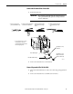
Install the Module Chapter 4
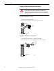
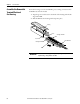
Recommendations for Wiring Your RTB
We recommend you follow these guidelines when wiring your RTB.
1. Begin wiring the RTB at the bottom terminals and move up.
2. Use a tie to secure the wires in the strain relief area of the RTB.
3. Order and use an extended-depth housing (catalog number 1756-TBE) for
applications that require heavy gauge wiring.
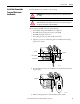
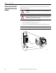
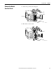
Wire the Module
Use the wiring diagrams below to wire your ControlLogix high-speed analog I/O
module.
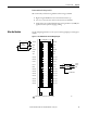
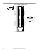
Figure 11 - 1756-IF4FXOF2F Current Mode Wiring Diagram
12
34
56
78
910
1112
1314
1516
1718
1920
2122
2324
2526
2728
2930
3132
3334
3536
+IN-1/V
IN-1/I
-IN-1
+IN-3/V
V OUT-1
IN-3/I
-IN-3
Not Used
Not Used
I OUT-1
RTN-1
2-wire
Transmitter
(+) (-)
i
42742
Shield Ground
Current
Output
Load
= Inline Field Device (strip chart recorder or meter)
A
A
A
Not Used
Not Used
Not Used
Not Used
Not Used
Not Used
Not Used
Not Used
Not Used
Not Used
Not Used
Not Used
Not Used
Not Used
+IN-0/V
IN-0/I
-IN-0
+IN-2/V
V OUT-0
IN-2/I
-IN-2
Not Used
Not Used
I OUT-0
RTN-0