
User Manual

50 Rockwell Automation Publication 1756-UM005B-EN-P - January 2013
Chapter 3 Module Features
Fault Reporting Example
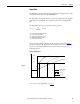
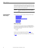
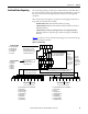
Figure 10 shows an example of what bits are set when a ControlLogix high-speed
analog I/O module reports a Wire Off condition on output channel 0. Three
events occur, beginning in the Output Channel Status word.
Figure 10 - Fault Reporting for Wire Off Condition
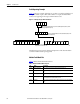
The following sections provide a listing and explanation of the bits included in
each of the module’s fault reporting words.
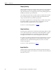
Module Fault Word Bits
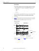
Table 8 defines the Module Fault word bits.
15 14 13 12 11
5 4 3210
5 4321076
When set, the I.Out0Fault bit (bit 4) sets the I.OutGroupFault bit (bit 13) and the
I.AnalogGroupFault bit (bit 15).
43175
8
When set, I.Out[0].WireOff bit sets the I.Out0Fault bit (bit 4) in the
Channel Fault word.
When the Wire Off condition on channel 0 occurs, the I.Out[0].WireOff bit (bit 5) in the
Output Channel Status word is set.
543210768
Table 8 - Module Fault Word Bit Descriptions
Bit Name Description
Bit 15 I.AnalogGroupFault Bit is set when any of the bits in the Channel Fault word are set.
Bit 14 I.InGroupFault Bit is set when any of the input channel fault bits in the Channel Fault word are
set.
Bit 13 I.OutGroupFault Bit is set when any of the output channel fault bits in the Channel Fault word are
set.
Bit 12 I.Calibrating Bit is set when any of the module’s channels are being calibrated. When this bit is
set, all used bits in the Channel Fault word are set.
Bit 11 I.CalFault Bit is set when an individual channel calibration fault bit, such as I.In[0].CalFault,
is set.