
User Manual

Rockwell Automation Publication 1756-UM005B-EN-P - January 2013 43
Module Features Chapter 3
Digital Filter
The digital filter smooths input data noise transients for all input channels on the
module. This feature is used on a per channel basis.
The digital filter value specifies the time constant for a digital first order lag filter
on the input. It is specified in units of milliseconds. A value of 0.0 disables the
filter.
The digital filter equation is a classic first order lag equation.
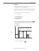
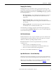
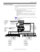
Using a step input change to illustrate the filter response, as shown in Figure 7
,
you can see that when the digital filter time constant elapses, 63.2% of the total
response is reached. Each additional time constant achieves 63.2% of the
remaining response.
Figure 7 - Filter Response
To see how to set the digital filter, see page 77.
Yn = Yn-1 + (X
n
– Y
n
-1)
[Δ t]
Δ t + TA
Yn = present output, filtered peak voltage (PV)
Yn-1 = previous output, filtered PV
Δt = module channel update time (seconds)
TA = digital filter time constant (seconds)
Xn = present input, unfiltered PV
0 0.01 0.5 0.99 Time in Seconds
16723
100%
63%
0
Amplitude
Unfiltered Input
TA = 0.01 s
TA = 0.5 s
TA = 0.99 s