
User Manual

118 Rockwell Automation Publication 1756-UM005B-EN-P - January 2013
Appendix B Tag Definitions
Output Data Tags
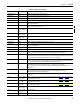
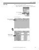
Table 17 lists the output data tags.
I.Out[0].ChanFault BOOL Copy of .Out0Fault in array with other channel status bits for ease of access.
I.Out[0].CalFault BOOL Status bit indicating if the channel has a bad calibration. Bad calibration means the last attempt to calibrate the channel failed
with an error and was aborted.
I.Out[0].WireOff BOOL Bit that indicates a wire has fallen off the output channel. This bit is functional only when C.Out[0].Range is set to operate in
0…20 mA mode.
I.Out[0].NotANumber BOOL Bit indicating the received output value from the controller (value in O.Data[0] tag) was an invalid IEEE floating point value.
When an invalid value is received, the output value holds its last known valid state.
I.Out[0].InHold BOOL Bit that indicates if the output channel is currently holding until the Output value sent to the module (value in O.Data[0] tag)
matches the current output value (value in O.Data[0] tag) within 0.1% of the channel’s full scale.
I.Out[0].RampAlarm BOOL Alarm bit that sets when the requested output value (C.Out[0].RampToRun) is set, and the difference between the new output
value requested and the current output exceeds the configured ramp limit (C.Out[0].MaxRampRate). The bit remains set until
ramping ceases unless the alarm is latched via C.Out[0].RampAlarmLatch.
I.Out[0].LLimitAlarm BOOL Alarm bit that sets when the requested output value (O.Data[0]) is below the configured low limit (C.Out[0].LowLimit). In this
case, the output stops at the configured low limit; the stop is reflected in the data echo. This bit remains set until the requested
output moves above the low limit unless latched by C.Out[0].LimitAlarmLatch.
I.Out[0].HLimitAlarm BOOL Alarm bit that sets when the requested output value (O.Data[0]) is above the configured high limit (C.Out[0].HighLimit). In this
case, the output stops at the configured high limit. The stop is reflected in the data echo. This bit remains set until the
requested output moves below the high limit unless latched by C.Out[0].LimitAlarmLatch.
I.Out[0].Data REAL Value the channel outputs (in engineering units) based on the configured scaling for the channel.
I.Out[1] AB:1756_IF4FXOF2F
_Struct_Out:I:0
Array for output channel 1. This is the same set of tags as listed for input channel 0, from I.Out[0].Status
to I.Out[0].Data,
except that this listing applies to channel 1.
I.CSTTimestamp Array of DINT Timestamp taken when input data is sampled. This value is listed as a 64-bit quantity in microseconds and coordinated across
the chassis. Must be addressed in 32-bit chunks as an array.
I.RollingTimestamp INT Timestamp taken when input data is sampled. This value is listed in milliseconds, relative solely to the individual module.
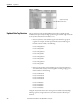
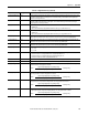
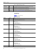
Table 16 - Input Data Tags (continued)
Tag Name Data Type Definition
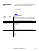
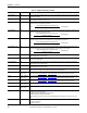
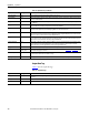
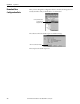
Table 17 - Output Data Tags
Tag Name Data Type Definition
O.Out[0].Data REAL[2] The channel output value in engineering units. The output value is measured and scaled, based on the configured scaling for
the channel.
O.Data[0] REAL Output Channel 0.
O.Data[1] REAL Output Channel 1.