
User Manual

Rockwell Automation Publication 1756-UM005B-EN-P - January 2013 117
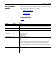
Tag Definitions Appendix B
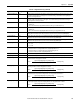
I.AnalogGroupFault BOOL Indicates if a channel fault has occurred on any channel.
I.InGroupFault BOOL Indicates if a channel fault has occurred on any input channel.
I.OutGroupFault BOOL Indicates if a channel fault has occurred on any output channel.
I.Calibrating BOOL Indicates if a calibration is currently in progress on any channel.
I.CalFault BOOL Status bit indicating if any channel has a bad calibration. Bad calibration means the last attempt to calibrate the channel failed
with an error and was aborted.
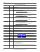
I.LastUpdateIndex DINT Returns the number of the last archive sample performed by the module before data was sent to the controller. This tag equals
19 when the RPI is greater than (20 * RTS).
I.Input AB:1756_IF4FXOF2F
_Struct_Archiving:S:
0[20]
An array that stores channel data for each of the 20 archive samples (0…19).
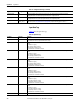
I.In AB:1756_IF4FXOF2F
_Struct_Int:I:0[2]
Input array structure.
I.In[0] AB:1756_IF4FXOF2F
_Struct_In:I:0
Channel array for input 0.
I.In[0].Status INT Collection of individual channel status bits.
I.In[0].ChanFault BOOL Copy of .In0Fault in array with other channel status bits for ease of access.
I.In[0].CalFault BOOL Status bit indicating if the channel has a bad calibration. Bad calibration means the last attempt to calibrate the channel failed
with an error and was aborted.
I.In[0].Underrange BOOL Alarm bits indicating the channel’s input is less than the minimum detectable input signal.
I.In[0].Overrange BOOL Alarms bit indicating the channel’s input is greater than the maximum detectable input signal.
I.In[0].RateAlarm BOOL Alarm bit that sets when the input channel’s rate of change exceeds the configured In[0].RateAlarmLimit. Remains set until the
rate change drops below the configured limit unless latched via In[0].RateAlarmLatch in the configuration.
I.In[0].LAlarm BOOL Low alarm bits that sets when the input signal moves beneath the configured low alarm trigger point, In[0].LAlarmLimit.
Remains set until the input signal moves above the trigger point, unless latched via In[0].ProcessAlarmLatch or the input is still
within the configured alarm deadband, In[0].AlarmDeadband, of the low alarm trigger point.
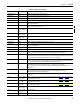
I.In[0].HAlarm BOOL High alarm bit that sets when the input signal moves above the configured high alarm trigger point, In[0].HAlarmLimit.
Remains set until the input signal moves below the trigger point, unless latched via In[0].ProcessAlarmLatch or the input is still
within the configured alarm deadband, In[0].AlarmDeadband, of the high alarm trigger point.
I.In[0].LLAlarm BOOL Low low alarm bit that sets when the input signal moves beneath the configured low low alarm trigger point,
In[0].LLAlarmLimit. Remains set until the input signal moves above the trigger point, unless latched via
In[0].ProcessAlarmLatch or the input is still within the configured alarm deadband, In[0].AlarmDeadband, of the low low
alarm trigger point.
I.In[0].HHAlarm BOOL High high alarm bit that sets when the input signal moves above the configured high high alarm trigger point,
In[0].ProcessAlarmLimit. Remains set until the input signal moves below the trigger point, unless latched via
In[0].AlarmDeadband, of the high high alarm trigger point.
I.In[0].Data REAL The channel input signal represented in engineering units. The input signal is measured and then scaled based on the user
configuration.
I.In[1] AB:1756_IF4FXOF2F
_Struct_In:I:0
Array for input channel 1. This is the same set of tags as listed for input channel 0, from I.In[0].Status
to I.In[0].Data, except
that this listing applies to channel 1.
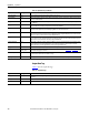
I.In[2] AB:1756_IF4FXOF2F
_Struct_In:I:0
Array for input channel 2. This is the same set of tags as listed for input channel 0, from I.In[0].Status
to I.In[0].Data, except
that this listing applies to channel 2.
I.In[3] AB:1756_IF4FXOF2F
_Struct_In:I:0
Array for input channel 3. This is the same set of tags as listed for input channel 0, from I.In[0].Status to I.In[0].Data, except
that this listing applies to channel 3.
I.Out AB:1756_IF4FXOF2F
_Struct_In:I:0[2]
Output array structure.
I.Out[0] AB:1756_IF4FXOF2F
_Struct_In:I:0
Output channel array.
I.Out[0].Status INT Collection of individual channel status bits.
Table 16 - Input Data Tags (continued)
Tag Name Data Type Definition