
User Manual

114 Rockwell Automation Publication 1756-UM005B-EN-P - January 2013
Appendix B Tag Definitions
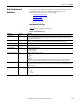
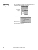
C.In[0].DigitalFilter REAL A non-zero value enables the filter. The value serves as a time constant in milliseconds that can be used in a first order lag filter
to smooth the input signal
C.In[0].RateAlarmLimit REAL The trigger point for the rate alarm status bit, which will set if the input signal changes at a rate faster than the configured rate
alarm. Configured in engineering units per second.
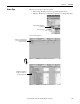
C.In[0].LowSignal REAL One of four points used in scaling. The low signal is in terms of the input signal units and corresponds to the low engineering
term when scaled. The scaling equation is as follows:
C.In[0].HighSignal REAL One of four points used in scaling. The high signal is in terms of the input signal units and corresponds to the high engineering
term when scaled. The scaling equation is as follows:
C.In[0].LowEngineering REAL One of four points used in scaling. The low engineering helps determine the engineering units the signal values scale into. The
low engineering term corresponds to the low signal value. The scaling equation used is as follows:
C.In[0].HighEngineering REAL One of four points used in scaling. The high engineering helps determine the engineering units the signal values scale into.
The high engineering term corresponds to the high signal value. The scaling equation used is as follows:
C.In[0].LAlarmLimit REAL The low alarm trigger point. This value causes the I.In[0].LAlarm to trigger when the input signal moves beneath the
configured trigger point, in engineering units.
C.In[0].HAlarmLimit REAL The high alarm trigger point. This value causes the I.In[0].HAlarm to trigger when the input signal moves above the configured
trigger point, in engineering units.
C.In[0].LLAlarmLimit REAL The low low alarm trigger point. This value causes the I.In[0].LLAlarm to trigger when the input signal moves beneath the
configured trigger point, in engineering units.
C.In[0].HHAlarmLimit REAL The high high alarm trigger point. This value causes the I.In[0].HHAlarm to trigger when the input signal moves above the
configured trigger point, in engineering units.
C.In[0].AlarmDeadband REAL Forms a deadband around the process alarms, which causes the corresponding process alarm status bit to remain set until the
input moves beyond the trigger point by greater than the amount of the alarm deadband.
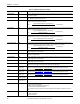
C.In[1] AB:1756_IF4FXOF2F
_Struct_In:C:0
Master structure beneath which configuration parameters for input channel 1 are set. This is the same set of tags as listed for
input channel 0, from C.In[0].AlarmDisable
to C.In[0].AlarmDeadband, except that this listing applies to channel 1.
C.In[2] AB:1756_IF4FXOF2F
_Struct_In:C:0
Master structure beneath which configuration parameters for input channel 2 are set. This is the same set of tags as listed for
input channel 0, from C.In[0].AlarmDisable
to C.In[0].AlarmDeadband, except that this listing applies to channel 2.
C.In[3] AB:1756_IF4FXOF2F
_Struct_In:C:0
Master structure beneath which configuration parameters for input channel 3 are set. This is the same set of tags as listed for
input channel 0, from C.In[0].AlarmDisable
to C.In[0].AlarmDeadband, except that this listing applies to channel 3.
C.Out AB:1756_IF4FXOF2F
_Struct_Out:C:0[2]
C.Out[0] AB:1756_IF4FXOF2F
_Struct_Out:C:0
Master structure beneath which configuration parameters for output channel 0 are set.
C.Out[0].HoldForInit BOOL When this bit is set, and one of the following occurs:
• Module initial connection (powerup)
• Module transition from Program mode back to Run mode
• Module reestablishes communication after fault
The bit configures the channel to hold its present state until initialized with a value within 0.1% of full scale of its current
value.
C.Out[0].AlarmDisable Disables all alarms for the channel
0 = Alarms are not disabled
1 = Alarms are disabled
Table 15 - Configuration Data Tags (continued)
Tag Name Data Type Definition
Data =
(Signal-LowSignal)(HighEngineering-LowEngineering)
High Signal - Low Signal
+ Low Engineering
Data =
(Signal-LowSignal)(HighEngineering-LowEngineering)
High Signal - Low Signal
+ Low Engineering
Data =
(Signal-LowSignal)(HighEngineering-LowEngineering)
High Signal - Low Signal
+ Low Engineering
Data =
(Signal-LowSignal)(HighEngineering-LowEngineering)
High Signal - Low Signal
+ Low Engineering