
User Manual

Rockwell Automation Publication 1756-UM005B-EN-P - January 2013 113
Tag Definitions Appendix B
Data Tag Names and
Definitions
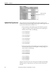
The set of tags associated with your high-speed analog module depends on the
communication format you choose during configuration. For each
communication format, there are three sets of tags:
• Configuration Data Tags
• Input Data Tags
• Output Data Tags
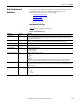
Configuration Data Tags
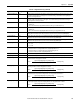
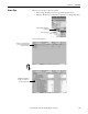
Table 15 lists the configuration data tags.
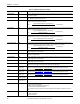
Table 15 - Configuration Data Tags
Tag Name Data Type Definition
C.ProgToFaultEn BOOL Determines how the outputs behavior if a communication fault occurs when the output module is in Program mode. When
set, the bit causes the outputs to transition to their programmed fault state. If not set, outputs remain in their configured
program state when the fault occurs.
C.SynchModInputs BOOL Enables synchronization of input sampling between multiple 1756-IF4FXOF2F/A modules in the same chassis. All modules
with this feature enabled attempt to sample inputs simultaneously, based on their RealTimeSample settings.
C.RealTimeSample REAL Determines how often the input signal is to be sampled in milliseconds with a decimal point
C.In[0] Struct Master structure beneath which configuration parameters for input channel 0 are set.
C.In[0].AlarmDisable BOOL Disables all alarms for the channel
0 - Alarms are not disabled
1 - Alarms are disabled
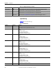
C.In[0].ProcessAlarmLatch BOOL Enables latching for all four process alarms:
• Low
• Low low
• High
• High high
If this feature is enabled, the triggered alarm remains latched in the set position, even if the condition causing the alarm
disappears. Once an alarm is latched, you must unlatch it via the Logix Designer application or a message instruction.
C.In[0].RateAlarmLatch BOOL Enables latching for the rate alarm. If this feature is enabled, the triggered alarm remains latched in the set position, even if
the condition causing the alarm disappears. Once an alarm is latched, you must unlatch it via the Logix Designer application or
a message instruction.
C.In[0].Range INT Configures the channel's input range as follows:
0 = -10…10V
1 = 0 …5V
2 = 0 …10V
3 = 0…20 mA