Installation Instructions ControlLogix™ Hydraulic Servo Module Catalog Number 1756-HYD02 To: See page: Obtain a User Manual 1 Note the Power Requirements 4 Identify Module Components 5 Install the Module 6 Key the Module and Removable Terminal Block/Interface Module 7 Wire a Removable Terminal Block (RTB) 8 Wire to a Servo Module 9 Assemble the Removable Terminal Block and the Housing 12 Install the Removable Terminal Block onto the Module 12 Checking the LED Indicators 13 Remove the
ControlLogix™ Hydraulic Servo Module Important User Information Because of the variety of uses for the products described in this publication, those responsible for the application and use of these products must satisfy themselves that all necessary steps have been taken to assure that each application and use meets all performance and safety requirements, including any applicable laws, regulations, codes and standards.
ControlLogix™ Hydraulic Servo Module 3 Environment and Enclosure ATTENTION ! This equipment is intended for use in a Pollution Degree 2 industrial environment, in overvoltage Category II applications (as defined in IEC publication 60664-1), at altitudes up to 2000 meters without derating. This equipment is considered Group 1, Class A industrial equipment according to IEC/CISPR Publication 11.
ControlLogix™ Hydraulic Servo Module Removal and Insertion Under Power WARNING ! When you insert or remove the module while backplane power is on, an electrical arc can occur. This could cause an explosion in hazardous location installations. Be sure that power is removed or the area is nonhazardous before proceeding. Repeated electrical arcing causes excessive wear to contacts on both the module and its mating connector. Worn contacts may create electrical resistance that can affect module operation.
ControlLogix™ Hydraulic Servo Module 5 Identify Module Components You received two components with your order: · 1756-HYD02 module · RTB door label If you did not receive these components, contact your Rockwell Automation representative. This module mounts in a 1756 chassis and uses a separately-ordered RTB or a Bulletin 1492 Interface Module (IFM)(1) to connect all field-side wiring.
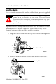
ControlLogix™ Hydraulic Servo Module Install the Module You can install or remove the module while chassis power is applied. WARNING ! When you insert or remove the module while backplane power is on, an electrical arc can occur. This could cause an explosion in hazardous location installations. Be sure that power is removed or the area is nonhazardous before proceeding. Repeated electrical arcing causes excessive wear to contacts on both the module and its mating connector.
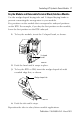
ControlLogix™ Hydraulic Servo Module 7 Key the Module and Removable Terminal Block/Interface Module Use the wedge-shaped keying tabs and U-shaped keying bands to prevent connecting the wrong wires to your module. Key positions on the module that correspond to unkeyed positions on the RTB. For example, if you key the first position on the module, leave the first position on the RTB unkeyed. 1. To key the module, insert the U-shaped band, as shown. U-shaped bands 20850–M 2.
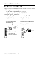
ControlLogix™ Hydraulic Servo Module Wire a Removable Terminal Block (RTB) Your 1756-HYD02 module uses two types of RTBs (each RTB comes with housing) to connect wiring. · Cage clamp - Catalog number 1756-TBCH · Spring clamp - Catalog number 1756-TBS6H Connect the wires as shown below. Spring Clamp RTB Cage Clamp RTB 1. Strip 7/16 inch (11mm) maximum length of wire. 1. Strip 3/8 inch (9.5mm) maximum length of wire. 2. Insert the screwdriver into the inner hole of the RTB. 2.
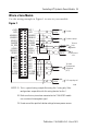
ControlLogix™ Hydraulic Servo Module 9 Wire to a Servo Module Use the wiring example in Figure 1 to wire to your module.
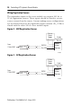
ControlLogix™ Hydraulic Servo Module Wiring Registration Sensors The registration inputs to the servo module can support 24V dc or 5V dc registration sensors. These inputs should be wired to receive source current from the sensor. Current sinking sensor configurations are not allowed because the registration input common (IN_ COM) is shared with the other 24V dc servo module inputs.
ControlLogix™ Hydraulic Servo Module 11 Wiring the Home Limit Switch Input The home limit switch inputs to the servo module are designed for 24V dc nominal operation. These inputs should be wired for current sourcing operation. Figure 4 24 V dc Power Supply + – From 1756-HYD02 HOME IN_COM General cable C0720 43396 Wiring the OK Contacts A set of isolated solid- state OK relay contacts is provided for optional interface to an E- stop string, which controls power to the associated pumps.
ControlLogix™ Hydraulic Servo Module Assemble the Removable Terminal Block and the Housing 1. Align the grooves at the bottom of the housing with the side edges of the RTB. Groove Side edge of the RTB Groove Strain relief area Side edge of the RTB 2. Slide the RTB into the housing until it snaps into place.
ControlLogix™ Hydraulic Servo Module 13 Checking the LED Indicators The module uses a single bi-colored LED to indicate module OK status and bi-colored LED indicators to show individual feedback (FDBK) and drive (DRIVE) status for both axes. During power up, the module completes an indicator test. The OK indicator turns red for 1 second and then turns to flashing green if the module passes all its self tests.
ControlLogix™ Hydraulic Servo Module If the OK indicator displays: The module status is: Take this action: Flashing red light One of the following: · A major recoverable failure has occurred. · A communication fault, timer fault, or non-volatile memory storage (NVS) update is in progress. · The OK contact has opened. If an NVS update is in progress, complete the NVS update. If an NVS update is not in progress: · Check the Servo Fault word for the source of the error.
ControlLogix™ Hydraulic Servo Module 15 The table below offers an explanation of the FDBK indicator. If the FDBK indicator displays: The module status is: Take this action: Off The axis is not used. Flashing green light The axis is in the normal servo loop inactive state. None. The servo axis state can be changed by executing motion instructions. Steady green light The axis is in the normal servo loop active state. None. The servo axis state can be changed by executing motion instructions.
ControlLogix™ Hydraulic Servo Module Understanding Module Status Using the DRIVE Indicator HYDRAULIC Drive indicators AX0 AX1 FDBK FDBK DRIVE DRIVE OK The table below offers an explanation of the DRIVE indicator. If the DRIVE indicator displays: The module status is: Off One of the following: · The axis is not used. · The axis is a positiononly axis type. Take this action: · None, if the axis is not used or is a position- only type.
ControlLogix™ Hydraulic Servo Module 17 If the DRIVE indicator displays: The module status is: Flashing red light The axis drive output is in the shutdown state. · Check for faults that may have generated this state. · Execute the Shutdown Reset motion instruction. · Resume normal operation. Steady red light The axis drive is faulted. · Check the drive status. · Clear the Drive Fault condition at the drive. · Clear the servo fault condition using the Motion Axis Fault Reset instruction.
ControlLogix™ Hydraulic Servo Module Remove the Removable Terminal Block from the Module If you need to remove the module, you must remove the RTB first. WARNING ! When you insert or remove the module while backplane power is on, an electrical arc can occur. This could cause an explosion in hazardous location installations. Be sure that power is removed or the area is nonhazardous before proceeding. Before removing the module, you must remove the RTB. 1.
ControlLogix™ Hydraulic Servo Module 19 1756-HYD02 Specifications Number of axes Servo loop Type Gain resolution Absolute position range Rate 2 axes maximum Proportional, integral and differential (PID) with Feed-Forwards and Directional scaling 32- bit floating point 230,000 LDT counts 500Hz to 4kHz (Selectable) Module location 1756 ControlLogix chassis Module keying Electronic Power dissipation 5.5W maximum Thermal dissipation 18.77 BTU/hr Backplane current 5.1V dc @ 700mA and 24V dc @ 2.
ControlLogix™ Hydraulic Servo Module Registration inputs Type 24V dc input voltage Maximum on Minimum on Maximum off 5V dc input voltage Maximum on Minimum on Maximum off Input impedance 24V dc input 5V dc input Response time (position latched) Optically isolated, current sinking input +24V dc nominal 26. 4V dc 18. 5V dc 3.5V dc +5V dc nominal 5.5V dc 3.7V dc 1.5V dc 1.2 kW 9.
ControlLogix™ Hydraulic Servo Module 21 Isolation Voltage User to System 30V continuous RTB keying User-defined Field wiring arm 36-position RTB (1756-TBCH or -TBS6H)(1) RTB screw torque (cage clamp) 4.4 inch-pounds (0.4Nm) maximum Conductors Wire size Category Screwdriver blade width for RTB #22 to #14 AWG (0.324 to 2.08 sq. mm) stranded(1) 3/ 64 inch (1.2 mm) insulation maximum 2(2), (3) 1/8 inch (3.
ControlLogix™ Hydraulic Servo Module ESD Immunity IEC 61000-4-2: 6kV contact discharges 8kV air discharges Radiated RF Immunity IEC 61000-4-3: 10V/m with 1kHz sine-wave 80%AM from 80MHz to 2000MHz 10V/m with 200Hz 50% Pulse 100%AM at 900Mhz EFT/B Immunity IEC 61000-4-4: ±2kV at 5kHz on signal ports Surge Transient Immunity IEC 61000-4-5: +2kV line-earth (CM) on shielded ports Conducted RF Immunity IEC 61000-4-6: 10Vrms with 1kHz sine-wave 80%AM from 150kHz to 80MHz Enclosure Type Rating None (
ControlLogix™ Hydraulic Servo Module 23 The following information applies when operating this equipment in hazardous locations: Informations sur l’utilisation de cet équipement en environnements dangereux : Products marked “CL I, DIV 2, GP A, B, C, D” are suitable for use in Class I Division 2 Groups A, B, C, D, Hazardous Locations and nonhazardous locations only. Each product is supplied with markings on the rating nameplate indicating the hazardous location temperature code.
Rockwell Automation Support Rockwell Automation tests all of our products to ensure that they are fully operational when shipped from the manufacturing facility. If you are experiencing installation or startup problems, please review the troubleshooting information contained in this publication first. If you need technical assistance to get your module up and running, please contact Customer Support (see the table below); our trained technical specialists are available to help.