
Instruction Manual

Publication 1756-UM525A-EN-P - June 2003 63
Using the 1756-HYD02 Module Features Chapter 4
Tune Tab
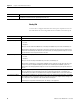
The table below lists the configurable features available on the Tune tab.
Feature: Definition:
Travel Limit Sets the axis’ travel limit during the tune test. If the hydraulic module determines that the axis will not be
able to complete the tuning process before exceeding the tuning travel limit, it will terminate the tuning
profile and report that this limit was exceeded.
Speed Sets the maximum speed for the tune process. This value should be set to the desired maximum operating
speed of the axis (in engineering units) prior to running the tune test.
Direction Sets the direction of the tuning motion profile. Negative indicates reverse direction; positive indicates
forward direction.
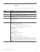
Tune Selects the gains to be determined by the tuning test:
• Position Error Integrator
• Velocity Feedforward
• Output Filter
• Velocity Error Integrator
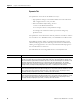
Start Tuning Begins the tuning test. If the tuning process completes successfully, the following attributes are set:
• Gains tab - Set the following attributes here:
• Velocity Feedforward Gain (if checked under Tune, above)
• Position Proportional Gain and Position Integral Gain (if checked under Tune, above)
• Dynamics tab - Set the following attributes here:
• Maximum Velocity
• Maximum Acceleration
• Maximum Deceleration
• Output tab - Set the following attributes here:
• Velocity Scaling
• Low Pass Output Filter (see Note, below)
• Limits - The Position Error Tolerance attribute is set on this tab.
You can use this selection to adjust bandwidth values as needed. During tuning, if the controller detects a
high degree of tuning inertia, it enables the Low Pass Output Filter and calculates and sets a value for Low
Pass Output Filter Bandwidth. Executing a Tune operation automatically saves all changes to axis properties.
ATTENTION: This tuning procedure may cause axis motion with the controller in program mode.