ControlLogix Hydraulic Servo Module User Manual Catalog Numbers 1756-HYD02
Important User Information Solid state equipment has operational characteristics differing from those of electromechanical equipment. Safety Guidelines for the Application, Installation and Maintenance of Solid State Controls (publication SGI-1.1 available from your local Rockwell Automation sales office or online at http://literature.rockwellautomation.com) describes some important differences between solid state equipment and hardwired electromechanical devices.
Table of Contents Preface Using This Manual . . . . . . . . . . . . . . . . . . . . . . . . . . . . . . . . . . . . . . . . . . 7 Who Should Use This Manual. . . . . . . . . . . . . . . . . . . . . . . . . . . . . . . . . 7 The Purpose of This Manual . . . . . . . . . . . . . . . . . . . . . . . . . . . . . . . . . . 7 Related Documentation . . . . . . . . . . . . . . . . . . . . . . . . . . . . . . . . . . . . . . 8 Chapter 1 What is the 1756-HYD02 Module? What the Module Does . . . . . . . . . . . . .
Table of Contents Chapter 3 Configuring the 1756-HYD02 Module Using RSLogix 5000 Configuration Software. . . . . . . . . . . . . . . . . . . . 31 Overview of the Configuration Process . . . . . . . . . . . . . . . . . . . . . . . . 32 Creating a New Module . . . . . . . . . . . . . . . . . . . . . . . . . . . . . . . . . . . . . 33 Configuring General Module Features . . . . . . . . . . . . . . . . . . . . . . . . . 35 Configuring the Axes Features . . . . . . . . . . . . . . . . . . . . . . . . . . . . .
Table of Contents Chapter 5 Troubleshooting the 1756-HYD02 Module What This Chapter Contains . . . . . . . . . . . . . . . . . . . . . . . . . . . . . . . . . 77 Using the Status Indicators . . . . . . . . . . . . . . . . . . . . . . . . . . . . . . . . . . 77 Using the OK Indicator . . . . . . . . . . . . . . . . . . . . . . . . . . . . . . . . . . . . . 78 Using the FDBK Indicator . . . . . . . . . . . . . . . . . . . . . . . . . . . . . . . . . . 79 Using the DRIVE Indicator . . . . . . . . . . . . . .
Table of Contents 6 Publication 1756-UM525A-EN-P - June 2003
Preface Using This Manual This preface describes how to use this manual. Who Should Use This Manual To effectively use this manual, you should be able to program and operate the Rockwell Automation ControlLogix controllers to efficiently use your ControlLogix Hydraulic Servo module. In this manual, we also refer to the module as the 1756-HYD02 module.
Preface Preface Related Documentation The following table lists related ControlLogix documentation: Publication Number Publication Description 1756-IN580 ControlLogix Hydraulic Servo Module Installation Instructions Provides instructions for installing, wiring, and troubleshooting your 1756-HYD02 module.
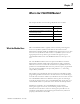
Chapter 1 What is the 1756-HYD02 Module? This chapter describes the ControlLogix Hydraulic Servo module. For more information about: What the Module Does See page: What the Module Does 9 Using A ControlLogix Hydraulic Servo Module in the ControlLogix System 10 Certifying Agency Approvals 11 Preventing Electrostatic Discharge 12 Removal and Insertion Under Power 12 THe 1756-HYD02 module is typically used for accurate positioning and control of a hydraulic cylinder.
Chapter 1 What is the 1756-HYD02 Module? Using A ControlLogix Hydraulic Servo Module in the ControlLogix System A ControlLogix Hydraulic Servo module mounts in a ControlLogix chassis and uses a removable terminal block (RTB) or interface module (IFM) to connect all field-side wiring. Before you install and use your module you should have already: • installed and grounded a ControlLogix chassis and power supply. To install these products, refer to the publications listed in on page 7.
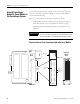
What is the 1756-HYD02 Module? Chapter 1 The table below lists the physical features on the ControlLogix Hydraulic Servo module. ControlLogix Hydraulic Servo Module Physical Features Certifying Agency Approvals Feature: Description: ControlLogix backplane connector The interface to the ControlLogix system; it connects the module to the backplane. Connectors pins Input/output and grounding connections are made to the module through these pins with the use of an RTB.
Chapter 1 What is the 1756-HYD02 Module? Preventing Electrostatic Discharge The 1756-HYD02 module is sensitive to electrostatic discharge. ATTENTION This equipment is sensitive to electrostatic discharge, which can cause internal damage and affect normal operation. Follow these guidelines when you handle this equipment: • Touch a grounded object to discharge potential static. • Wear an approved grounding wriststrap. • Do not touch connectors or pins on component boards.
Chapter 2 Installing the 1756-HYD02 Module What This Chapter Contains This chapter describes how to install the 1756-HYD02 module.
Chapter 2 Installing the 1756-HYD02 Module Installing the Module You can install or remove the module while chassis power is applied. ATTENTION The module is designed to support Removal and Insertion Under Power (RIUP). However, when you remove or insert an RTB with field-side power applied, unintended machine motion or loss of process control can occur. Exercise extreme caution when using this feature. 1. Align circuit board with top and bottom chassis guides. Printed Circuit Board 20861-M 2.
Installing the 1756-HYD02 Module Keying the Removable Terminal Block Chapter 2 Key the RTB to prevent inadvertently connecting the incorrect RTB to your module. When the RTB mounts onto the module, keyed positions match up. For example, if you place a U-shaped keying band in position #4 on the module, you cannot place a wedge-shaped tab in #4 on the RTB or your RTB will not mount on the module. Use a unique keying pattern for each slot in the chassis. 1.
Chapter 2 Installing the 1756-HYD02 Module Connecting Wiring This module uses an RTB or a Bulletin 1492 Interface Module (IFM)(1) to connect all field-side wiring. Use an extended-depth cover (1756-TBE) for applications with heavy gauge wiring or requiring additional routing space. The maximum wire gauge that can be used with the 1756-HYD02 module is #14 AWG (2.08 sq. mm) stranded. If you are using an RTB to connect wiring to you module, follow the directions beginning below.
Installing the 1756-HYD02 Module Chapter 2 Spring Clamp 1. Insert the screwdriver into the outer hole of the RTB. 2. Insert the wire into the open terminal and remove the screwdriver. Strain relief area 20860-M Recommendations for Wiring Your RTB TIP Consider the following when wiring your RTB: • Begin wiring the RTB at the bottom terminals and move up. • Use a tie to secure the wires in the strain relief area of the RTB. • The jumper bar part number is 97739201.
Chapter 2 Installing the 1756-HYD02 Module Use the wiring example in Figure to wire to your module.
Installing the 1756-HYD02 Module Chapter 2 Wiring Registration Sensors The registration inputs to the servo module can support 24V or 5V registration sensors. These inputs should be wired to receive source current from the sensor. Current sinking sensor configurations are not allowed because the registration input common (IN_ COM) is shared with the other 24V servo module inputs.
Chapter 2 Installing the 1756-HYD02 Module Wiring the Home Limit Switch Input The home limit switch inputs to the servo module are designed for 24V nominal operation. These inputs should be wired for current sourcing operation. 24V dc Field Power Supply + – From 1756-HYD02 HOME IN_COM General cable C0720 43396 Wiring the OK Contacts A set of isolated solid- state OK relay contacts is provided for optional interface to an E- stop string, which controls power to the associated pumps.
Installing the 1756-HYD02 Module Chapter 2 Connecting LDTs to Your Hydraulic Module Because the number of LDTs that you can connect to your 1756-HYD02 module is continually changing, we cannot list all the available LDTs here. Figure shows the connections for two example LDT types–Temposonic and Balluff–that were available for connection to the 1756-HYD02 module at the time of this printing. Remember, there are other suppliers with compatible LDTs.
Chapter 2 Installing the 1756-HYD02 Module Figure shows an application wiring example using a 1-axis loop with a differential LDT input. (The power supplies and servo amplifiers are user-supplied.) 24V Power Supply PC with RSLogix 5000™ + –C Drive Output ControlLogix controller 1756-HYD02 + OUT – OUT CHASSIS Servo or Proportional Amplifier IMPORTANT: This module’s analog output require an external amplifier to drive the valve.
Installing the 1756-HYD02 Module Assembling The Removable Terminal Block and the Housing Chapter 2 Removable housing covers the wired RTB to protect wiring connections when the RTB is seated on the module. 1. Align the grooves at the bottom of each side of the housing with the side edges of the RTB. Housing Groove Side edge of RTB Groove Strain relief area Side edge of RTB RTB 20858-M 2. Slide the RTB into the housing until it snaps into place.
Chapter 2 Installing the 1756-HYD02 Module Choosing the Extended-Depth Housing There are two housing options you must consider when wiring your ControlLogix Hydraulic Servo module. When you order an RTB for your I/O module, you receive a standard-depth housing with the RTB. If your application uses heavy gauge wiring, you can order an extended-depth housing. This housing does not come with an RTB.
Installing the 1756-HYD02 Module Chapter 2 Suggestions for Using the Extended-Depth Housing TIP Consider the following when deciding to use an extended-depth housing on your I/O module. It is recommended you use the 1756-TBE when: • using >36 18AWG wires • using >23 14AWG wires Cabinet Size Considerations With the Extended-Depth Housing When you use an extended-depth housing (1756-TBE), the module depth is increased.
Chapter 2 Installing the 1756-HYD02 Module Installing the Removable Terminal Block Install the RTB onto the module to connect wiring. ATTENTION Shock hazard exists. If the RTB is installed onto the module while the field-side power is applied, the RTB will be electrically live. Do not touch the RTB’s terminals. Failure to observe this caution may cause personal injury. The RTB is designed to support Removal and Insertion Under Power (RIUP).
Installing the 1756-HYD02 Module Chapter 2 2. Press quickly and evenly to seat the RTB on the module until the latches snap into place. Locking tab 20854-M 3. Slide the locking tab down to lock the RTB onto the module.
Chapter 2 Installing the 1756-HYD02 Module Removing the Removable Terminal Block If you need to remove the module from the chassis, you must first remove the RTB from the module. ATTENTION Shock hazard exists. If the RTB is removed from the module while the field-side power is applied, the module will be electrically live. Do not touch the RTB’s terminals. Failure to observe this caution may cause personal injury. The RTB is designed to support Removal and Insertion Under Power (RIUP).
Installing the 1756-HYD02 Module Removing the Module from the Chassis Chapter 2 Follow the steps below to remove the 1756-HYD02 module from the ControlLogix chassis. 1. Push in the top and bottom locking tabs. Locking tabs 20856-M 2. Pull module out of the chassis.
Chapter 2 Installing the 1756-HYD02 Module Chapter Summary and What’s Next 30 In this chapter, you read about Installing the 1756-HYD02 Module. Chapter 3 explains Configuring the 1756-HYD02 Module.
Chapter 3 Configuring the 1756-HYD02 Module This chapter describes how to configure a ControlLogix Hydraulic Servo module.
Chapter 3 Configuring the 1756-HYD02 Module Overview of the Configuration Process Figure shows an overview of the configuration process. New Module 1. Select the Hydraulic Servo module. 2. Choose a Major Revision General Tab Name Description Slot number Comm.
Configuring the 1756-HYD02 Module Creating a New Module Chapter 3 After you have started RSLogix 5000 and created a controller, you must create a new module. The wizard allows you to create a new module and configure it. IMPORTANT You must be offline when you create a new module. 1. If your application is online, go offline. Use this pull-down menu to go offline 2. Access the Select Module Type screen. A. Select I/O Configuration. B. Right-click to see the menu. C. Select New Module.
Chapter 3 Configuring the 1756-HYD02 Module 3. Select the module type. B. Make sure the Major Revision number matches the label on the side of your module A. Select the Hydraulic Servo module C. Click here. 4. Begin configuration on the naming screen. E. Select the slot in which your module resides. A. Name the module. B. Add a description (optional). F. Choose an Electronic Keying method. A detailed explanation of this field is provided on page 44. C.
Configuring the 1756-HYD02 Module Configuring General Module Features Chapter 3 You see the series of wizard screens after the naming screen. Use these screens to configure general features on the 1756-HYD02 module. Inhibit the connection to the module If you want a Major Fault on the Controller to occur if there is connection failure with the I/O module while in Run mode, click here This Fault box is empty when you are offline.
Chapter 3 Configuring the 1756-HYD02 Module Configuring the Axes Features You must create an axis before you can associate it with a channel on the 1756-HYD02 module. 1. Create the new axis tag as shown below. Click on New Axis to create a new axis tag that will contain the axis data. The New Tag pop-up screen appears, as shown below. The new axis tag must be: ² named ² of the AXIS_SERVO data type ² of the controller scope 2. Access the axis properties as shown below. A.
Configuring the 1756-HYD02 Module Chapter 3 3. Configure the axis properties on the wizard screens that appear. The General screen is shown below. Click on the necessary tab and make changes to the axis properties. For a full description of all the configurable features available on the Axis properties wizard, see the Using Axes Features section beginning on page 52.
Chapter 3 Configuring the 1756-HYD02 Module Editing Configuration After you set configuration for a module, you can review and change it. You can change configuration data and download it to the controller while online. This is called dynamic reconfiguration. Your freedom to change some configurable features, though, depends on whether the controller is in Remote Run mode or Program mode.
Configuring the 1756-HYD02 Module Reconfiguring Module Parameters in Run Mode Chapter 3 Your module can operate in Remote Run mode or Hard Run mode. You can only change any configurable features that are enabled by RSLogix 5000 in Remote Run mode. If any feature is disabled in either Run mode, change the controller to Program mode and make the necessary changes. Reconfiguring Module Parameters in Program Mode Follow these steps to change configuration in Program mode. 1.
Chapter 3 Configuring the 1756-HYD02 Module Chapter Summary and What’s Next In this chapter you read about: • configuring ControlLogix Hydraulic Servo modules • editing module configuration • configuration tags Chapter 4 explains Using the 1756-HYD02 Module Features.
Chapter 4 Using the 1756-HYD02 Module Features This chapter describes the 1756-HYD02 module’s configurable features.
Chapter 4 Using the 1756-HYD02 Module Features What This Chapter Contains Using General Module Features This chapter is broken into the two sections. Section: Description: Begins on page: Using General Module Features This section describes features that affect the module in a general sense. For example, the 1756-HYD02 module offers electronic keying options that you can configure to set the degree of protection your application needs against using the wrong 1756-HYD02 module.
Using the 1756-HYD02 Module Features Chapter 4 Module Fault Reporting The 1756-HYD02 module provides hardware and software indication when a module fault has occurred. The module’s LED fault indicator and the RSLogix 5000 programming software graphically display faults; the software also offers a message describing the nature of the fault. This feature allows you to determine how your module has been affected and what action should be taken to resume normal operation.
Chapter 4 Using the 1756-HYD02 Module Features Electronic Keying The electronic keying feature automatically compares the expected module, as shown in the RSLogix 5000 I/O Configuration tree, to the physical module before I/O communication begins. You can use electronic keying to help prevent communication to a module that does not match the type and revision expected.
Using the 1756-HYD02 Module Features Chapter 4 General Tab IMPORTANT Changing electronic keying selections online may cause the I/O communication connection to the module to be disrupted and may result in a loss of data. Exact Match Exact Match keying requires all keying attributes, that is, Vendor, Product Type, Product Code (catalog number), Major Revision, and Minor Revision, of the physical module and the module created in the software to match precisely in order to establish communication.
Chapter 4 Using the 1756-HYD02 Module Features Automatic Firmware Update for the module via the Firmware Supervisor feature from a Logix5000 controller. EXAMPLE In the following scenario, Exact Match keying prevents I/O communication: • The module configuration is for a 1756-IB16D module with module revision 3.1. The physical module is a 1756-IB16D module with module revision 3.2. In this case, communication is prevented because the Minor Revision of the module does not match precisely.
Using the 1756-HYD02 Module Features Chapter 4 Compatible Keying Compatible Keying indicates that the module determines whether to accept or reject communication. Different module families, communication adapters, and module types implement the compatibility check differently based on the family capabilities and on prior knowledge of compatible products. Compatible Keying is the default setting.
Chapter 4 Using the 1756-HYD02 Module Features can avoid the case of a physical module rejecting the keying request because it is an earlier revision than the one configured in the software. EXAMPLE In the following scenario, Compatible Keying prevents I/O communication: • The module configuration is for a 1756-IB16D module with module revision 3.3. The physical module is a 1756-IB16D module with module revision 3.2.
Using the 1756-HYD02 Module Features EXAMPLE Chapter 4 In the following scenario, Compatible Keying allows I/O communication: • The module configuration is for a 1756-IB16D module with module revision 2.1. The physical module is a 1756-IB16D module with module revision 3.2. In this case, communication is allowed because the major revision of the physical module is higher than expected and the module determines that it is compatible with the prior major revision.
Chapter 4 Using the 1756-HYD02 Module Features Disabled Keying Disabled Keying indicates the keying attributes are not considered when attempting to communicate with a module. Other attributes, such as data size and format, are considered and must be acceptable before I/O communication is established. With Disabled Keying, I/O communication may occur with a module other than the type specified in the I/O Configuration tree with unpredictable results. We generally do not recommend using Disabled Keying.
Using the 1756-HYD02 Module Features EXAMPLE Chapter 4 In the following scenario, Disable Keying allows I/O communication: • The module configuration is for a 1756-IA16 digital input module. The physical module is a 1756-IB16 digital input module. In this case, communication is allowed because the two digital modules share common data formats.
Chapter 4 Using the 1756-HYD02 Module Features Using Axes Features Associated axes can be connected to channels 0 and 1 on the 1756-HYD02 module during initial configuration or on the Associated Axes tab of the module’s properties in RSLogix 5000. IMPORTANT When configuring Servo Axes features, remember the following: • The 1756-HYD02 module only works with AXIS_SERVO data type tags.
Using the 1756-HYD02 Module Features Chapter 4 Feature: Definition: Ellipsis button (. . .) Opens the Motion Group Properties dialog box for the Assigned Motion Group, where you can edit the properties of the Assigned Motion Group. If no Motion Group is assigned to this axis, this button is disabled. New Group Opens the New Tag dialog box, where you can create a new Motion Group tag. This button is enabled only if you have not created a Motion Group tag.
Chapter 4 Using the 1756-HYD02 Module Features Motion Planner Tab The table below lists the configurable features available on the Motion Planner tab. Feature: Definition: Output Cam Execution Targets Use this field to set the maximum number of output cams that will be used on the axis. This value allocates controller memory to allow the motion planner to build CAM association tables.
Using the 1756-HYD02 Module Features Chapter 4 Feature: Definition: Master Delay Compensation Master Delay Compensation helps a slave approach zero tracking error when gearing or camming to the actual position of a master axis. When camming or gearing off of actual feedback, some delay exists between when the master position data is generated and when the controller acts on that data for a slave. This delay causes a slave response to lag behind a master.
Chapter 4 Using the 1756-HYD02 Module Features Units Tab Use the Units tab to determine the programming and configuration units used to define your motion axis. When RSLogix 5000 software is online and the controller transitions to hard run, or the axis loop is on (i.e., active), then all the attributes on this tab transition to a read only state. When any attribute transitions to a read only state, then any pending attribute changes are reverted.
Using the 1756-HYD02 Module Features Chapter 4 Servo Tab For an axis of the data type AXIS_SERVO, configured for Servo operation (i.e. closed loop operation) in the General tab of this dialog box, use the SERVO tab to: • configure an external drive. • configure the drive fault input. • select up to two axis attributes whose status can be monitored. The table below lists the configurable features available on the Servo tab.
Chapter 4 Using the 1756-HYD02 Module Features Feedback Tab Use the Feedback tab to select a feedback type. RSLogix 5000 displays multiple feedback types for the 1756-HYD02 module. At this release of the 1756-HYD02 module, only the LDT type is available. The table below lists the configurable features available on the LDT feedback option. Feature: Definition: LDT Type Selection determines what type of LDT provides feedback to the 1756-HYD02 module.
Using the 1756-HYD02 Module Features Chapter 4 Feature: Definition: Absolute Feedback Offset The absolute offset is used to place the machine zero point at the desired location relative to the zero point of the LDT. The LDT zero point is inside the transducer head and physically unattainable. Calculated Values:Conversion Constant Calculation derived from values based on the configuration values entered for the LDT.
Chapter 4 Using the 1756-HYD02 Module Features Homing Tab The table below lists the configurable features available on the Homing tab. Feature: Definition: Mode Select one of the following homing modes: • Active: The homing sequence automatically moves the axis to find the home switch. Active homing sequences use the trapezoidal velocity profile. • Passive: Homing redefines the absolute position of the axis on the occurrence of a home switch.
Using the 1756-HYD02 Module Features Chapter 4 Feature: Definition: Active Home Sequence Group: Direction For active homing sequences, except for the Immediate Sequence type, select the desired homing direction: • Forward Bi-directional - The following events occur: a. The axis moves forward at the rate specified in the Speed field until a homing event occurs (i.e. a switch turns ON). b.
Chapter 4 Using the 1756-HYD02 Module Features Feature: Definition: Return Speed The moving axis’ speed in the return leg(s) of an active homing sequence. The home return speed specified should be less than the maximum speed and greater than zero. Hookup Tab Use this tab to configure and initiate axis hookup test sequences for the axis. The table below lists the configurable features available on the Hookup tab.
Using the 1756-HYD02 Module Features Chapter 4 Tune Tab The table below lists the configurable features available on the Tune tab. Feature: Definition: Travel Limit Sets the axis’ travel limit during the tune test. If the hydraulic module determines that the axis will not be able to complete the tuning process before exceeding the tuning travel limit, it will terminate the tuning profile and report that this limit was exceeded. Speed Sets the maximum speed for the tune process.
Chapter 4 Using the 1756-HYD02 Module Features Dynamics Tab The parameters on this tab can be edited in two ways: • Type parameter changes in the fields available on this tab and use the OK or Apply buttons to save your edits. • Edit in the Manual Adjust dialog. To do so: a. Click on the Manual Tune button. b. Use the spin controls to edit parameter settings. Your changes are saved the moment a spin control changes any parameter value.
Using the 1756-HYD02 Module Features Chapter 4 Gains Tab Use this tab to perform the following offline functions: • Adjust gain values that have been automatically set by the tuning process, that is, in the Tune tab. • Manually configure gains for the position loop. The 1756-HYD02 module uses a single digital control loop with proportional, integral, differential and feed-forward gains.
Chapter 4 Using the 1756-HYD02 Module Features The table below lists the configurable features available on the Gains tab. Feature: Definition: Position Gains: Proportional Position gain is used with position error to correct an axis’ position. The proportional gain specifies the amount of correction (velocity command) that the controller applies for each unit of position error. You must determine how much position error is expected while an axis runs at a specific speed.
Using the 1756-HYD02 Module Features Chapter 4 Feature: Definition: Position Gains: Differential Velocity Error is multiplied by the Position Gains: Differential to produce a component to the analog output or Velocity Command that ultimately attempts to correct for the velocity error, creating a damping effect. Thus, increasing the Position Gains: Differential results in smoother motion, enhanced acceleration, reduced overshoot, and greater system stability.
Chapter 4 Using the 1756-HYD02 Module Features Output Tab Use the Output tab for offline configuration of the following: • Scaling values that are used to generate gains. • The analog loop’s low-pass digital output filter. The parameters on this tab can be edited in two ways: • Type parameter changes in the fields available on this tab and use the OK or Apply buttons to save your edits. • Edit in the Manual Adjust dialog. To do so: a. Click on the Manual Tune button. b.
Using the 1756-HYD02 Module Features Chapter 4 Feature: Definition: Direction Scaling Ratio The directional scaling ratio compensates for the difference in the maximum speed in the extend vs. retract direction on single-ended hydraulic cylinders. Different piston areas on the cap (blind) end compared to the rod end of the cylinder cause the speed difference.
Chapter 4 Using the 1756-HYD02 Module Features Limits Tab Use the Limits tab to set the following parameters offline: • • • • • Enable positive and negative software travel limits Set maximum positive and negative software travel limits Configure Position Error Tolerance Configure Position Lock Tolerance Set the module’s Output Limit The parameters on this tab can be edited in two ways: • Type parameter changes in the fields available on this tab and use the OK or Apply buttons to save your edits.
Using the 1756-HYD02 Module Features Chapter 4 Feature: Definition: Position Error Tolerance Specifies how much position error the axis loop tolerates before issuing a position error fault. This value is interpreted as a +/- quantity. For example, setting Position Error Tolerance to 0.75 position units means that a position error fault will be generated whenever the position error of the axis is greater than 0.75 or less than -0.75 position units.
Chapter 4 Using the 1756-HYD02 Module Features Offset Tab Use the Offset tab to make offline adjustments to the following values: • Deadband Compensation • Velocity Offset • Output Offset The parameters on this tab can be edited in two ways: • Type parameter changes in the fields available on this tab and use the OK or Apply buttons to save your edits. • Edit in the Manual Adjust dialog. To do so: a. Click on the Manual Tune button. b. Use the spin controls to edit parameter settings.
Using the 1756-HYD02 Module Features Chapter 4 Feature: Definition: Backlash Compensation: Reversal Offset Use this feature to compensate for positional inaccuracy introduced by mechanical backlash. For example, power-train type applications require a high level of accuracy and repeatability during machining operations. Lost motion is often generated by a number of mechanical components that may introduce inaccuracies and that are subject to wear over their lifetime.
Chapter 4 Using the 1756-HYD02 Module Features Feature: Definition: Output Offset Corrects the problem of axis “offset”, by adding a fixed voltage value (not to exceed +/-10V) to the analog output value. Use a value to achieve near zero axis velocity when the uncompensated analog output value is zero. When interfacing to a valve on a hydraulic axis, it is necessary to compensate for the effect of drive offset.
Using the 1756-HYD02 Module Features Chapter 4 Table describes the possible actions if any of the faults listed in Table occurs Fault: Definition: Shutdown If a fault action is set to Shutdown, when the associated fault occurs: • servo action status is immediately disabled, • the drive output is zeroed, and • the appropriate drive enable output is deactivated.
Chapter 4 Using the 1756-HYD02 Module Features Tag Tab Use this tab to change the name and description of the axis. When you are online, all of the parameters on this tab transition to a read-only state, and cannot be modified. If you go online before you save your changes, all pending changes revert to their previously-saved state. The table below lists the features available on the Tag tab. Some of these features cannot be changed on this screen however.
Chapter 5 Troubleshooting the 1756-HYD02 Module What This Chapter Contains This chapter describes how to troubleshoot the 1756-HYD02 module.
Chapter 5 Troubleshooting the 1756-HYD02 Module Using the OK Indicator The module’s OK indicator is shown below. OK indicator 43454 The table below explains the OK indicator. OK Indicator Displays If the OK indicator displays: The module status is: Off The module is not operating. Take this action: • Apply chassis power. • Verify the module is completely inserted into the chassis and backplane.
Troubleshooting the 1756-HYD02 Module Using the FDBK Indicator Chapter 5 The module’s FDBK indicators are shown in Figure . Make sure that any transducer used with the 1756-HYD02 module uses an external interrogation signal. Feedback indicators 43454 The table below explains the FDBK indicators. FDBK Indicator Displays If the FDBK indicator displays: The module status is: Take this action: Off The axis is not used.
Chapter 5 Troubleshooting the 1756-HYD02 Module Using the DRIVE Indicator The module’s DRIVE indicators are shown in Figure . Drive indicators 43454 The table below explains the DRIVE indicator. DRIVE Indicator Displays If the DRIVE indicator displays: The module status is: Take this action: Off One of the following: If the axis is being used and is not a position-only axis type, make sure the module is configured, an axis tag has been associated with the module, and the axis type is servo.
Troubleshooting the 1756-HYD02 Module Using RSLogix 5000 to Troubleshoot the Module Chapter 5 You can also use the RSLogix 5000 programming software to detect and diagnose problems with the ControlLogix Hydraulic Servo module.
Chapter 5 Troubleshooting the 1756-HYD02 Module Fault Message in Status Line The module status line appears in the lower left corner of each configuration tab. It provides a brief explanation of the module status and reports Faulted when a fault has occurred on the module. Explanation of the module fault Notification in Axis Structure Use the Tag Monitor to view controller tags. A fault has occurred for any point that lists the number one (1) in the Fault line.
Appendix A Specifications Number of axes Servo loop Type Gain resolution Absolute position range Rate Proportional, integral and differential (PID) with Feed-Forwards and Directional scaling 32- bit floating point 230,000 LDT counts 500Hz to 4kHz (Selectable) Module location 1756 ControlLogix chassis Module keying Electronic Power dissipation 5.5W maximum Thermal dissipation 18.77 BTU/hr. Backplane current 5.1V dc @ 700mA and 24V dc @ 2.
Appendix A Specifications Servo output Type Voltage range Voltage resolution Load Maximum offset Gain error Analog voltage ±10V dc 16 bits 5.6 kOhms resistive minimum 25 mV ±4% All other outputs Type Operating voltage Maximum Operating current Solid-state isolated relay contacts +24V dc nominal 26. 4V dc 75 mA Isolation Voltage User to System 30V continuous RTB keying User-defined Field wiring arm 36-position RTB (1756-TBCH or -TBS6H)(2) RTB screw torque (cage clamp) 4.4 inch-pounds (0.
Specifications Radiated RF Immunity IEC 61000-4-3: 10V/m with 1kHz sine-wave 80%AM from 80MHz to 2000MHz 10V/m with 200Hz 50% Pulse 100%AM at 900Mhz EFT/B Immunity IEC 61000-4-4: ±2kV at 5kHz on signal ports Surge Transient Immunity IEC 61000-4-5: +2kV line-earth (CM) on shielded ports Conducted RF Immunity IEC 61000-4-6: 10Vrms with 1kHz sine-wave 80%AM from 150kHz to 80MHz Enclosure Type Rating None (open-style) Certifications (when product is marked) Publication 1756-UM525A-EN-P - June 2003
Appendix A Specifications Notes: 86 Publication 1756-UM525A-EN-P - June 2003
Glossary Broadcast Data transmissions to all address or functions Bumpless reconfiguration A reconfiguration in which the real time data connection to the module is not closed and reopened. Communications are never interrupted and configuration data is applied to the module immediately. This works best in a single owner-controller system.
Glossary Disable keying An electronic keying protection mode that requires no attributes of the physical module and the module configured in the software to match Download The process of transferring the contents of a project on the workstation into the controller Electronic keying A feature where modules can be requested to perform an electronic check to make sure that the physical module is consistent with what was configured by the software Exact match An electronic keying protection mode that requires
Glossary Major revision A module revision that is updated any time there is a functional change to the module Minor revision A module revision that is updated any time there is a change to the module that does not affect its function or interface Owner-controller The controller that creates and stores the primary configuration and communication connection to a module Position loop Part of motion control firmware responsible for: · comparing measured position with command position to determine a position er
Glossary Run mode In this mode, the following events occur: · Controller program is executing · Inputs are actively producing data. · Outputs are actively controlled Service A system feature that is performed on user demand, such as fuse reset or diagnostic latch reset Status indicators Indicators on the front of the ControlLogix Hydraulic Servo module that display the general status of the module and specific status of individual feedback and drive conditions for the axes connected to the module.
Index Numerics 1756-SYNCH module Using with the 1756-HYD02 module 9 A Agency approvals 11 Axes properties Configuring in RSLogix 5000 36 Conversion tab 59 Conversion constant 59 Positioning mode 59 Dynamics tab 64 Maximum acceleration 64 Maximum deceleration 64 Maximum velocity 64 Fault actions tab 74 Drive fault 74 Feedback 74 Feedback noise 74 Position error 74 Soft overtravel 74 Feedback tab 58 Absolute feedback offset 59 Calibration constant 58 LDT type 58 Length 58 Recirculations 58 Scaling 58 Gains t
Index C Cage clamp RTB 16 Class I Division 2 compliance 11 Configurable features of the 1756-HYD02 module Axes features 52-76 General module features 42-51 Configuration Configuring the axes features 36 Dynamic reconfiguration 38 Editing configuration 38-39 Overview of the process 32 Reconfiguring parameters in program mode 39 Reconfiguring parameters in run mode 39 Using RSLogix 5000 31-40 I Inhibiting the module 35 Interface module (IFM) 10, 16 K Keying Electronic 34, 44-?? Mechanical 15 L Linear disp
Index Removal and insertion under power (RIUP) 12, 14 RSLogix 5000 31-40 Configuring the axes features 36 Conversion tab 59 Dynamics tab 64 Electronic keying 34 Fault actions tab 74 Feedback tab 58 Gains tab 65 General tab 52 Homing tab 60 Hookup tab 62 Limits tab 70 Motion planner tab 54 Offset tab 72 Output tab 68 Reconfiguring parameters in program mode 39 Reconfiguring parameters in run mode 39 Servo tab 57 Tag tab 76 Tune tab 63 Units tab 56 Using the software in troubleshooting 81-82 S Servo update
Index 94 Publication 1756-UM525A-EN-P - June 2003
How Are We Doing? Your comments on our technical publications will help us serve you better in the future. Thank you for taking the time to provide us feedback. You can complete this form and mail (or fax) it back to us or email us at RADocumentComments@ra.rockwell.com. Pub. Title/Type ControlLogix Hydraulic Servo Module Cat. No. 1756-HYD02 Pub. No. 1756-UM525A-EN-P Pub. Date June 2003 Part No. 957678-84 Please complete the sections below.
PLEASE FASTEN HERE (DO NOT STAPLE) PLEASE FOLD HERE NO POSTAGE NECESSARY IF MAILED IN THE UNITED STATES BUSINESS REPLY MAIL FIRST-CLASS MAIL PERMIT NO.
Rockwell Automation Support Rockwell Automation provides technical information on the Web to assist you in using its products. At http://support.rockwellautomation.com, you can find technical manuals, a knowledge base of FAQs, technical and application notes, sample code and links to software service packs, and a MySupport feature that you can customize to make the best use of these tools.