
Manual

Rockwell Automation Publication 1756-UM007C-EN-P - November 2011
Install and Wire the ControlLogix High-speed Counter Module 49
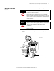
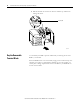
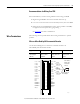
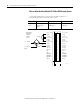
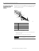
Wire a PHOTOSWITCH Series 10,000 Photoelectric Sensor
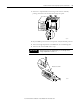
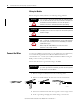
Use the table and diagram to connect wiring to a series 10,000 photoelectric
sensor.
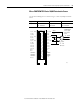
Application A1 Connections B1 Connections Z1 Connections
Any Black - A1 12…24V DC
Blue - A1 Return
Jumper B1 12…24V DC
to B1 Return
White - Z1 12…24V DC
Blue - Z1 Return
Jumper
Black
Blue
White
Not used
10…30V DC
Z1 (12…24V)
Z1 (5V)
Z1 (RET)
B1 (12…24V)
B1 (5V)
B1 (RET)
A1 (12…24V)
A1 (5V)
A1 (RET)
Not used
Not used
Not used
Z0 (12…24V)
Z0 (5V)
Z0 (RET)
B0 (12…24V)
B0 (5V)
B0 (RET)
A0 (12…24V)
A0 (5V)
A0 (RET)
Not used
Not used
Not used
COMMON 0
COMMON 0
COMMON 0
DC-0(+)
Out 2
Out 3
COMMON 1
COMMON 1
COMMON 1
DC-1(+)
Out 0
Out 1
12…24V
DC Return
41603
PHOTOSWITCH
Series 10,000
Photoelectric
Sensor
2
4
6
8
10
12
14
16
18
20
22
24
26
28
30
32
34
36
1
3
5
7
9
11
13
15
17
19
21
23
25
27
29
31
33
35