
Manual

Rockwell Automation Publication 1756-UM007C-EN-P - November 2011
Install and Wire the ControlLogix High-speed Counter Module 45
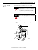
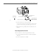
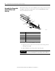
5. Connect the drain wire to a chassis mounting tab.
Use any chassis mounting tab that is designated as a functional signal
ground. The functional earth ground symbol appears near the tab.
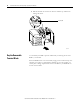
6. When the drain wire is grounded, connect the insulated wires to the
field-side.
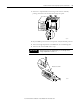
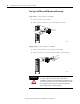
Connect Ungrounded End of the Cable
Follow these directions to connect the ungrounded end of the cable.
1. Cut the foil shield and drain wire back to the cable casing and apply
shrink wrap.
2. Connect the insulated wires to the RTB.
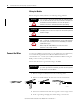
Chassis Mounting Tab
4 m or 5 m (#10 or #12)
Star Washer
Drain Wire with Ground Lug
4 m or 5 m (#10 or #12)
Phillips Screw and Star
Washer (or SEM Screw)
20918-M
Functional Earth
Ground Symbol