
Manual

Rockwell Automation Publication 1756-UM007C-EN-P - November 2011
20 Counter Modes
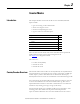
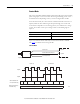
Encoder Mode
Encoder mode also counts incoming pulses. However, the phase relationship
between two input channels (A and B) determines whether the direction of the
count is up or down.
In Encoder x1 mode, an increasing count results when channel B is 90° ahead
of channel A. The count is initiated on the rising edge of channel A, and the
direction of the encoder is clockwise (positive).
The module produces a decreasing count when channel A is 90° ahead of
channel B. The count is initiated on the falling edge of channel A, and the
direction is counterclockwise (negative).
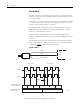
By monitoring both the number of pulses and the phase relationships of
signals A and B, you can accurately determine the position and direction of the
rotation.
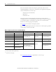
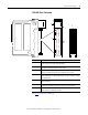
The illustration shows the phase relationships between channels A and B for
the x1 mode. Input Z is used in Encoder mode only if a Store Count mode is
enabled. See
page 23
for details on the Storage modes.
Encoder x1 Mode
Encoder
Input A
Input B
Input A
Input B
B Leads A 90°
A Leads B 90°
Input A
Input B
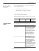
123 210
1756-HSC Module
Change
Accumulated Count
in Present Value Tag
Directional Frequency
in Totalizer Tag
Positive Frequency Negative Frequency
44889
. . .
Input Z (optional)