User Manual ControlLogix High-speed Counter Module Catalog Numbers 1756-HSC
Important User Information Solid-state equipment has operational characteristics differing from those of electromechanical equipment. Safety Guidelines for the Application, Installation and Maintenance of Solid State Controls (publication SGI-1.1 available from your local Rockwell Automation® sales office or online at http://www.rockwellautomation.com/literature/) describes some important differences between solid-state equipment and hard-wired electromechanical devices.
Summary of Changes This manual contains new and updated information. Changes throughout this revision are marked by change bars, as shown to the right of this paragraph. New and Updated Information This table contains the changes made to this revision. Topic Page The Attention and Warning tables have been updated.
Summary of Changes Notes: Rockwell Automation Publication 1756-UM007C-EN-P - November 2011
Table of Contents Preface About This Publication . . . . . . . . . . . . . . . . . . . . . . . . . . . . . . . . . . . . . . 9 Who Should Use This Manual. . . . . . . . . . . . . . . . . . . . . . . . . . . . . . . . . 9 Additional Resources . . . . . . . . . . . . . . . . . . . . . . . . . . . . . . . . . . . . . . . 10 Chapter 1 1756-HSC Module Features Introduction . . . . . . . . . . . . . . . . . . . . . . . . . . . . . . . . . . . . . . . . . . . . . . 11 What is a High-speed Counter Module? . . .
Table of Contents Two Types of RTBs (each RTB comes with housing) . . . . . . . . . Recommendations for Wiring Your RTB . . . . . . . . . . . . . . . . . . . Wire Terminations . . . . . . . . . . . . . . . . . . . . . . . . . . . . . . . . . . . . . . . . . Wire an Allen-Bradley 845 Incremental Encoder . . . . . . . . . . . . . Wire an Allen-Bradley Bulletin 872 3-Wire DC Proximity Sensor Wire a PHOTOSWITCH Series 10,000 Photoelectric Sensor . . . Assemble the Removable Terminal Block and Housing . . .
Table of Contents 7 Configuration Structure . . . . . . . . . . . . . . . . . . . . . . . . . . . . . . . . . . 87 Output Structure . . . . . . . . . . . . . . . . . . . . . . . . . . . . . . . . . . . . . . . 89 Input Structure. . . . . . . . . . . . . . . . . . . . . . . . . . . . . . . . . . . . . . . . . 91 Appendix C 1756-HSC Module History Introduction . . . . . . . . . . . . . . . . . . . . . . . . . . . . . . . . . . . . . . . . . . . . . . 93 1756-HSC Profile Overview . . . . . . . . . . . . .
Table of Contents Publication 1756-UM007C-EN-P - November 2011
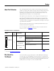
Preface About This Publication The 1756 High-speed Counter module counts incoming pulses from pulse generators, counters, limit switches, and other devices, and can either return a count to the controller or activate on-board outputs for a specific action depending on your application. In the rest of this manual, we refer to the High-speed Counter module as the 1756-HSC module. The chapters in this manual focus on the configuration and operation of a ControlLogix® 1756-HSC/B module, firmware revision 3.
Preface Additional Resources These documents provide information related to the ControlLogix High-speed Counter Module. Resource Description 1756 ControlLogix I/O Technical Data, publication 1756-TD002 Provides specifications for the ControlLogix controllers, I/O modules, specialty modules, chassis, power supplies and accessories. ControlLogix System User Manual, publication 1756-UM001 Detailed description of how to use your ControlLogix operating system.
Chapter 1 1756-HSC Module Features Introduction The High-speed Counter Module (catalog number 1756-HSC) performs high-speed counting for industrial applications. This chapter provides an overview of the design and features of the 1756-HSC/B module. For other module series, firmware, and/or software information, see Appendix C.
1756-HSC Module Features This user manual also details the Frequency operational modes that are available depending on which one is required for your application. Frequency can be calculated in one of three ways: • frequency (rate measurement). • period rate. • continuous rate. All three Frequency modes determine the frequency of input pulses by counting pulses over a user-defined time interval.
1756-HSC Module Features Encoder and Sensor Compatibility 13 The most common applications using the 1756-HSC module also use the following Allen-Bradley products: • Allen-Bradley 845 incremental encoder • Allen-Bradley Bulletin 872 three-wire DC proximity sensor • PHOTOSWITCH® series 10,000 photoelectric sensor Additional encoders and sensors may be connected to and used with the ControlLogix 1756-HSC module.
1756-HSC Module Features Additional I/O Module Features The following items are additional features for ControlLogix I/O modules, including the 1756-HSC module. Feature Description Configuration software RSLogix 5000 software has a custom interface to configure your module. All module features can be enabled and disabled through the software. Module fault reporting I/O modules provide both hardware and software indications when a module fault occurs. Status indicators signal fault conditions.
1756-HSC Module Features 1756-HSC Parts Illustration 4 7 5 3 2 6 1 41623 Item Description 1 Backplane connector - The backplane interface for the ControlLogix system connects the module to the backplane. 2 Top and bottom guides - Guides provide assistance in seating the removable terminal block (RTB) onto the module. 3 Connector pins - Input/output, power, and grounding connections are made to the module through these pins with the use of an RTB.
1756-HSC Module Features Notes: Rockwell Automation Publication 1756-UM007C-EN-P - November 2011
Chapter 2 Counter Modes Introduction This chapter describes the Counter modes for the 1756-HSC/B module. Topics include: • • • • types of counting: counter and encoder. means of storing the counts. modes for manipulating the count. tags for control of on-board outputs.
Counter Modes • Encoder x1- This is a Bidirectional Count mode, counting up or down, using an incremental encoder with direction output. • Encoder x4 - This is a Bidirectional Count mode, using quadrature encoder signals, with four times the resolution of X1. The 1756-HSC/B module also offers the convenience of showing directional frequency by using any Counter mode. If the count value is increasing, the frequency is positive in the Totalizer tag.
Counter Modes 19 Counter Mode This is the 1756-HSC module’s default operational mode that counts incoming pulses using input A. You can control the starting and ending points of the accumulated count depending on how you have configured the module. In the Counter mode, the count increases or decreases based on the state of input B, which can be a random signal. If input B is high, the counter will count down.
Counter Modes Encoder Mode Encoder mode also counts incoming pulses. However, the phase relationship between two input channels (A and B) determines whether the direction of the count is up or down. In Encoder x1 mode, an increasing count results when channel B is 90° ahead of channel A. The count is initiated on the rising edge of channel A, and the direction of the encoder is clockwise (positive). The module produces a decreasing count when channel A is 90° ahead of channel B.
Counter Modes 21 Encoder x4 Encoder x4 mode is identical to x1, except this mode counts on the leading and trailing edges of A and B to provide a greater number of pulse counts. The greater the number of pulse counts the better the module can determine position. Input Z is used in Encoder mode only if a Store Count mode is enabled. See page 23 for details on the storage modes.
Counter Modes Preset Each of the two counters has one preset value associated with it. In the Encoder or Counter modes, the preset value represents a reference point (or value) from which the module begins counting. The module can count either up or down from the preset value. The preset value itself is entered during module configuration. However, you must enter a preset command from either the RSLogix 5000 programming software or ladder logic before it becomes active.
Counter Modes 23 Rollover in Output tag When using the HSC Data-extended Comm Format while configuring the module, the Rollover tag will be found in both the Configuration and Output tag areas. The Configuration tag value is populated during software configuration with the Logix5000 controller, and sent to the module upon powerup, defining its behavior. This value will continue to define module behavior as long as the corresponding tag in the Output area is zero.
Counter Modes Store and Continue Mode Incoming Pulses 10 11 12 13 14 15 16 17 18 19 20 Present Value Tag in Logix Controller ...10 11 12 13 14 15 16 17 18 19 20 ... 8 8 13 13 13 13 13 18 18 18 Z-Input Stored Value Tag in Logix Controller 44900 In the Store and Continue mode, the module: • reads the Present Value and places it into the Stored Value on the leading edge of Input Z. • continues to accumulate the Present Value based on presets and incoming pulses.
Counter Modes 25 Store and Reset, Wait, and Start Incoming Pulses 10 11 12 13 14 15 16 17 18 19 20 Present Value Tag in Logix Controller 10 11 0 0 0 1 2 3 0 0 0 1 2 ... 11 11 11 11 11 3 3 3 3 3 Z-Input Stored Value Tag in Logix Controller 44902 In the Store and Reset, Wait, and Start mode, the module: • reads the Present Value and places it into the Stored Value on the leading edge of Input Z and resets the count to zero (0) in the Present Value.
Counter Modes IMPORTANT You have the option of selecting either the rising or falling edge of the gate/reset pulse. When the Invert Z Value box is checked on the Counter Configuration tab, the state of the Z input is reversed as illustrated in the four Store modes. For example, in the Store and Reset, and Start mode using the Invert Z, the falling edge of the pulse on Input Z will store the count value in the Stored Value tag and reset the Present Value tag to zero.
Counter Modes 27 For example, the ‘Output Turns ON’ tag is set for a value of 2000 and the ‘Output Turns OFF’ tag is set for a value of 5000. 2001…4999 Accumulated Count in Present Value Tag 2000 5000 10686 In the illustration, the: • output turns On at the Present Value of 2000. • output remains energized for 3000 additional counts. • output turns Off at the Present Value of 5000. Tying Outputs to Counters You can jumper any of the outputs to any of the counter inputs on the module’s RTB.
Counter Modes Notes: Rockwell Automation Publication 1756-UM007C-EN-P - November 2011
Chapter 3 Frequency Modes Introduction This chapter describes the frequency modes that are available with the 1756-HSC/B module when using the HSC Data-extended Comm Format. The Frequency modes are: • Frequency - number of input pulses per user-defined time interval. • Period Rate - number of sampled, internal 4 MHz pulses per user-defined number of incoming pulses, with outputs updated at the end of the sample period with the Present Value, Totalizer, and Stored Value tags.
Frequency Modes The difference between the Period Rate and Continuous Rate modes is the outputs are dynamic (On/Off) throughout the sample period for Continuous Rate while Period Rate outputs are updated only at the end of the sample period. Your desired output behavior should determine whether one uses Period Rate or Continuous Rate modes. See page 35 for details. Where Frequency Values are Stored in Tags Mode Description Present Value Tag Frequency No.
Frequency Modes Sample Period for Frequency Mode As previously mentioned, the Sample Period is a user-defined time frame to count the number of incoming pulses for calculating frequency. This fixed, sample period of time can be set by varying the Scaler tag, which can range from 10…2000 in 10 ms increments. For example, a Scaler value of 100 = 100 ms. The default value is 1 second. IMPORTANT A Scaler tag value of 0 equals a 1 second time period.
Frequency Modes Period Rate and Continuous Rate Modes These two Frequency-operational modes are identical in how they calculate frequency. They determine the frequency of input pulses by counting the number of internal 4 MHz clock pulses over a user-specified number of Z-input signal pulses defined by the Scaler. Frequency = .
Frequency Modes 33 As the frequency of the incoming pulse train increases, the number of sampled pulses from the 4 MHz clock decreases. Because accuracy is related to the number of 4 MHz pulses received over the sample period, the accuracy will decrease with increasing input frequencies at the Z-input. The decrease in accuracy can be lessened by scaling the input frequency through the use of the Scaler tag.
Frequency Modes The inverse relationship of the increase in frequency and decrease in sampled pulses is shown in the table. Inverse Relationship of Frequency and Sampled Pulses Input Frequency at Z-Input 2 Hz 5 Hz 10 Hz 20 Hz 50 Hz 100 Hz 200 Hz 500 Hz Scaler Value No.
Frequency Modes Output Operation 35 The Period Rate and Continuous Rate frequency operational modes differ in the operation of their respective on-board outputs. Both modes use count values that you enter in the ‘Output Turns On’ and ‘Output Turns Off ’ fields on the Output Configuration tab. These user-defined presets turn an output On and Off. These On and Off count values are compared to the internal 4 MHz counts returned in the Present Value tag.
Frequency Modes Period Rate /Continuous Rate Output Examples The following square waves illustrate the difference between Period Rate and Continuous Rate frequency operational modes. All square waves were initiated by applying a 50 Hz signal at the Input Z terminal of a counter configured for either Period Rate or Continuous Rate. The output configuration remained constant with an On value of 20,000 counts and an Off value of 80,001 counts.
Frequency Modes 37 Outputs in Period Rate and Continuous Rate with Scaler = 4 50 Hz at Z-Input 50% Duty Cycle Scaler Tag = 4 What the Counter Sees Internally With Scaler Tag = 4 Counter Idle Counter Times Width of Pulse 4 MHz = 160,000 Output State in Period Rate Scaler Tag = 4 Output OnValue Tag = 20,000 Output OffValue Tag = 80,001 4 MHz Count = 160,000 4 MHz Count = 160,000 Output State in Continuous Rate 4 MHz Count = 20,000 4 MHz Count = 80,000 4 MHz Count = 20,000 4 MHz Count = 80,000 4 MH
Frequency Modes Notes: Rockwell Automation Publication 1756-UM007C-EN-P - November 2011
Chapter 4 Install and Wire the ControlLogix High-speed Counter Module Introduction ATTENTION This chapter describes how to install and maintain the 1756-HSC module. If your module is already installed, proceed to page 55.
Install and Wire the ControlLogix High-speed Counter Module North American Hazardous Location Approval The following information applies when operating this equipment in hazardous locations. Informations sur l’utilisation de cet equipement en environnements dangereux. Products marked "CL I, DIV 2, GP A, B, C, D" are suitable for use in Class I Division 2 Groups A, B, C, D, Hazardous Locations and nonhazardous locations only.
Install and Wire the ControlLogix High-speed Counter Module Install the 1756-HSC Module 41 You can install or remove the module while chassis power is applied. WARNING When you insert or remove the module while backplane power is on, an electrical arc can occur. This could cause an explosion in hazardous location installations. Be sure that power is removed or the area is nonhazardous before proceeding.
Install and Wire the ControlLogix High-speed Counter Module 2. Slide the module into the chassis until the module’s top and bottom locking tabs ‘click’. Locking Tab 20862-M Key the Removable Terminal Block You should key the RTB to prevent inadvertently connecting the incorrect RTB to your module. When the RTB mounts onto the module, keying positions will match up.
Install and Wire the ControlLogix High-speed Counter Module 43 1. Insert the U-shaped band with the longer side near the terminals, pushing the band on the module until it snaps into place. 20850-M 2. Key the RTB in positions that correspond to unkeyed module positions. 3. Insert the wedge-shaped tab on the RTB with the rounded edge first. 4. Push the tab onto the RTB until it stops. IMPORTANT When keying your RTB and module, you must begin with a wedge-shaped tab in slot 6 or 7.
Install and Wire the ControlLogix High-speed Counter Module Wiring the Module Before wiring the module, adhere to the following wiring guidelines. WARNING If you connect or disconnect wiring while the field-side power is on, an electrical arc can occur. This could cause an explosion in hazardous location installations. Be sure that power is removed or the area is nonhazardous before proceeding. ATTENTION If multiple power sources are used, do not exceed the specified isolation voltage.
Install and Wire the ControlLogix High-speed Counter Module Functional Earth Ground Symbol 45 4 m or 5 m (#10 or #12) Star Washer Chassis Mounting Tab Drain Wire with Ground Lug 20918-M 4 m or 5 m (#10 or #12) Phillips Screw and Star Washer (or SEM Screw) 5. Connect the drain wire to a chassis mounting tab. Use any chassis mounting tab that is designated as a functional signal ground. The functional earth ground symbol appears near the tab. 6.
Install and Wire the ControlLogix High-speed Counter Module Two Types of RTBs (each RTB comes with housing) Cage clamp - catalog number 1756-TBCH 1. Insert the wire into the terminal. 2. Turn the screw clockwise to close the terminal on the wire. 20859-M Spring clamp - catalog number 1756-TBS6H 1. Insert the screwdriver into the outer hole of the RTB. 2. Insert the wire into the open terminal and remove the screwdriver.
Install and Wire the ControlLogix High-speed Counter Module 47 Recommendations for Wiring Your RTB We recommend that you follow these guidelines when wiring your RTB. 1. Begin wiring the RTB at the bottom terminals and move up. 2. Use a tie to secure the wires in the strain relief (bottom) area of the RTB. 3. Order and use an extended-depth housing (catalog number 1756-TBE) for applications that require heavy gauge wiring. See Appendix D for cable considerations.
Install and Wire the ControlLogix High-speed Counter Module Wire an Allen-Bradley Bulletin 872 3-Wire DC Proximity Sensor Use the table and diagram to connect the 1756-HSC module to an Allen-Bradley 872 three-wire DC proximity sensor. Application A0 Connections B0 Connections Z0 Connections PNP (Sourcing) Black - A0 12…24V DC Jumper B0 12…24V DC Jumper Z0 12…24V DC to B0 Return to Z0 Return N.O.
Install and Wire the ControlLogix High-speed Counter Module 49 Wire a PHOTOSWITCH Series 10,000 Photoelectric Sensor Use the table and diagram to connect wiring to a series 10,000 photoelectric sensor.
Install and Wire the ControlLogix High-speed Counter Module Assemble the Removable Terminal Block and Housing Removable housing covers the wired RTB to protect wiring connections when the RTB is seated on the module. Parts of the 1756-TBCH RTB (example below) are identified in the table. 1 2 3 2 5 3 4 20858-M Item Description 1 Housing cover 2 Groove 3 Side edge of RTB 4 RTB 5 Strain relief area Follow these steps to attach the RTB to the housing. 1.
Install and Wire the ControlLogix High-speed Counter Module Install the Removable Terminal Block 51 These steps show how to install the RTB onto the module to connect the wiring. WARNING When you connect or disconnect the Removable Terminal Block (RTB) with field side power applied, an electrical arc can occur. This could cause an explosion in hazardous location installations. Be sure that power is removed or the area is nonhazardous before proceeding.
Install and Wire the ControlLogix High-speed Counter Module 3. Slide the locking tab down to lock the RTB onto the module. 20854-M Remove the Removable Terminal Block If you need to remove the module from the chassis, you must first remove the RTB from the module. Do these steps to remove the RTB. WARNING When you connect or disconnect the Removable Terminal Block (RTB) with field side power applied, an electrical arc can occur. This could cause an explosion in hazardous location installations.
Install and Wire the ControlLogix High-speed Counter Module 53 3. Hold the spot marked PULL HERE and pull the RTB off the module. IMPORTANT Do not wrap your fingers around the entire door. A shock hazard exists. 20855-M Remove the Module from the Chassis Follow these steps to remove a module from its chassis. WARNING When you insert or remove the module while backplane power is on, an electrical arc can occur. This could cause an explosion in hazardous location installations.
Install and Wire the ControlLogix High-speed Counter Module 1. Push in the top and bottom locking tabs. 20856-M 2. Pull the module out of the chassis.
Chapter 5 Configure the 1756-HSC Module Introduction This chapter describes how to configure the 1756-HSC/B module, firmware revision 3.x, by using RSLogix 5000 programming software, version 18 and later. Your 1756-HSC module will not work until it has been configured. See Appendix C for profiles of the 1756-HSC/A. The instructions include firmware revisions 1.x and 2.x and RSLogix 5000 software versions 15…18.
Configure the 1756-HSC Module A remote chassis, also known as a networked chassis, contains the 1756-HSC module but not the module’s owner-controller. See page 57 for important information about running RSNetWorx™ software with a remote chassis. The illustration shows how the module communicates with its owner-controller. If connections are severed or compromised, the 1756-HSC module performs as configured, either setting all outputs to reset (On or Off) or continuous operations.
Configure the 1756-HSC Module 57 One of the following events occurs: • If the data is appropriate to the module found in the slot, a connection is made and operation begins. • If the configuration data is not appropriate, the data is rejected and an error message displays in the software. In this case, the configuration data can be inappropriate for any of a number of reasons.
Configure the 1756-HSC Module The timing of this ‘reserved’ spot may not coincide with the exact value of the RPI, but the control system guarantees that the owner-controller receives data at least as often as the specified RPI. As shown in the illustration, data from the remote chassis is sent to the ControlNet bridge module at a rate no slower than the configured RPI.
Configure the 1756-HSC Module 59 Use the Default Configuration 1756-HSC modules in the same chassis as the controller are ready to run as soon as the program download is complete. The default configuration for your module is the Counter operational mode, with none of the outputs tied to counters. If you choose to write a specific configuration for your application, you must access the module tags and change configuration information before downloading configuration to the owner-controller and module.
Configure the 1756-HSC Module The Select Module dialog box appears. 2. Click the ‘+’ next to Speciality for a list for this module group. 3. Select 1756-HSC/B and click OK. The New Module dialog box appears. 4. In the Name box, type a module name. 5. In the Slot box, enter the module’s slot number. 6. In the Description box, type an optional description for the module.
Configure the 1756-HSC Module 61 7. From the Comm Format pull-down menu, choose a communication format. See page 62 for a description of the formats and the associated tags that are created during the download. IMPORTANT Make sure you select the correct communication format for your application because you cannot change the selection after the program is downloaded with the controller. You will have to reconfigure the module to change the communication format. 8.
Configure the 1756-HSC Module Communication Format Options Multiple controllers can receive data being produced by a 1756-HSC module. The communication format determines: • whether a controller owns or just listens to the information. • the type of configuration options that are available. • the tags that are generated during the initial configuration. The following table describes the four communication formats available for the 1756-HSC/B module.
Configure the 1756-HSC Module 63 The table lists the mode number and assigned tags for the HSC Data and HSC Data-extended Comm Formats. The HSC Data format does not create the Totalizer tag, so directional frequency with the counters is not available. Communication Format Modes and Tags Comm Format = HSC Data (1756-HSC version 1.
Configure the 1756-HSC Module Set RPI The Connection tab on the Module Properties dialog box lets you enter a requested packet interval (RPI). The RPI guarantees the slowest rate at which the pulse count values will be produced to the owner-controller. The module’s actual data transfer rate may be faster than the RPI setting. But, the RPI provides a defined, maximum period of time when data is transferred to the owner-controller. 1. Choose from the options in the Connection tab.
Configure the 1756-HSC Module 65 Field Description Use Unicast Connection on EtherNet/IP Displays only for 1756-HSC modules using RSLogix 5000 software version 18 in a remote EtherNet/IP chassis. Use the default checkbox if there are no other controllers in ‘Listen’ mode. Clear the box if there are other ‘listening’ controllers in the system. Module Fault The fault box is empty if you are offline. The type of fault displays in the text box if a fault occurs when the 1756-HSC module is online. 2.
Configure the 1756-HSC Module The Counter Configuration dialog box appears. The dialog box is divided into two halves; one each for the respective channel (0, 1) inputs. 2. Choose counter parameters in the Counter Configuration tab. Field descriptions and procedures apply for both channel 0 and channel 1. Field Description Operational Mode Choose an operational mode based on your application requirements.
Configure the 1756-HSC Module Field Description Storage Mode Choose how the pulse count will be stored (with the mode selected in the above field) if required for an accumulated count. These are the values: 67 • • • • No Store Mode (default) Store and Continue Mode Store, Wait, and Resume Mode Store and Reset, Wait, and Start Mode • Store and Reset, and Start Mode See Storage Modes in Chapter 2 for details. Rollover Defaults to zero (0), which is the equivalent to a full count range (16,777,214).
Configure the 1756-HSC Module Field Description Use Filter A Select a filter for either Channel 0 and/or Channel 1. Use Filter B Use Filter Z See Filter Selections for how the filters affect the signal rate. Invert Z Value Box becomes active when a Storage mode is selected other than ‘No Store Mode.’ When active, Input Z reverses reading the rising or falling edge of the pulse depending on previous usage.
Configure the 1756-HSC Module 69 The Output Configuration dialog box appears. 2. Choose output parameters in the Output Configuration dialog box. Field Description Output Click one of four output buttons to configure the respective output. Tie to Counter Choose a mode to determine if an output is tied to a counter. These are the values: • Not Tied to Counter (default) • Tied to Counter 0 • Tied to Counter 1 Output State in Fault Mode Output State in Program Mode Defaults to Off for both options.
Configure the 1756-HSC Module Field Description First Value Output Turns ON Type values to turn the selected output On and Off, respectively. Each pair (First Value, Second Value) can be assigned to an output. First Value Output Turns OFF Second Value Output Turns ON Second Value Output Turns OFF The values can be set for the rising or falling edge of the window depending on whether the Invert Z Value is active for an operational mode.
Configure the 1756-HSC Module Copy Configuration (.C) Output, Rollover, Preset Tags to Output (.O) Tags 71 The configuration procedures previously described populated the Configuration tags (.C) in the controller memory. Starting with firmware revision 2 for the 1756-HSC module, some of these tags—output, preset, and rollover, are also populated in the Output tags (.O) to facilitate real-time changes of these parameters.
Configure the 1756-HSC Module 5. Type the following information: Source -- Local:3:C.Output[0] Dest -- Local:3:O.Output[0] Length -- 4 (this is the size of the array with 4 outputs: 0, 1, 2, 3) Your routine should look like the following example for a 1756-HSC module in a slot. 6. Repeat step 4 and step 5 to add two more CPS commands to the same rung. 7. Type the information as shown in the example.
Configure the 1756-HSC Module Electronic Keying 73 When you create a new module, you can choose how specific the keying must be when a module is inserted into the 1756-HSC module’s slot in the chassis. IMPORTANT Modules that are using Major Revision 3.x or later with RSLogix 5000 software versions 15...17 must use Compatible Keying. You must upgrade to version 18 if Exact Match is required.
Configure the 1756-HSC Module You can find revision information on the General tab of a module’s Properties dialog box. General Tab IMPORTANT Changing electronic keying selections online may cause the I/O communication connection to the module to be disrupted and may result in a loss of data.
Configure the 1756-HSC Module 75 Exact Match keying is also necessary to enable Automatic Firmware Update for the module via the Firmware Supervisor feature from a Logix5000 controller. EXAMPLE In the following scenario, Exact Match keying prevents I/O communication: The module configuration is for a 1756-IB16D module with module revision 3.1. The physical module is a 1756-IB16D module with module revision 3.2.
Configure the 1756-HSC Module Compatible Keying is the default setting. Compatible Keying allows the physical module to accept the key of the module configured in the software, provided that the configured module is one the physical module is capable of emulating. The exact level of emulation required is product and revision specific. With Compatible Keying, you can replace a module of a certain Major Revision with one of the same catalog number and the same or later, that is higher, Major Revision.
Configure the 1756-HSC Module EXAMPLE 77 In the following scenario, Compatible Keying allows I/O communication: The module configuration is for a 1756-IB16D module with module revision 2.1. The physical module is a 1756-IB16D module with module revision 3.2. In this case, communication is allowed because the major revision of the physical module is higher than expected and the module determines that it is compatible with the prior major revision.
Configure the 1756-HSC Module ATTENTION Be extremely cautious when using Disabled Keying; if used incorrectly, this option can lead to personal injury or death, property damage, or economic loss. If you use Disabled Keying, you must take full responsibility for understanding whether the module being used can fulfill the functional requirements of the application.
Configure the 1756-HSC Module EXAMPLE 79 In the following scenario, Disable Keying allows I/O communication: The module configuration is for a 1756-IA16 digital input module. The physical module is a 1756-IB16 digital input module. In this case, communication is allowed because the two digital modules share common data formats. Module Configuration Vendor = Allen-Bradley Product Type = Digital Input Module Catalog Number = 1756-IA16 Major Revision = 2 Minor Revision = 1 Communication is allowed.
Configure the 1756-HSC Module The Download dialog box appears. 3. Click Download.
Chapter 6 Module Diagnostics Introduction 1756-HSC Error Codes This chapter describes error codes and fault conditions to help you troubleshoot the 1756-HSC module. Topic Page 1756-HSC Error Codes 81 RSLogix 5000 Diagnostics 82 Troubleshoot the 1756-HSC Module 84 Errors are displayed on the Connection tab of the Module Properties dialog box in RSLogix 5000 software and in the .EXERR field of the message variable when you reconfigure the module.
Module Diagnostics Counter Configuration Errors Error Code Definition 16#0051, 16#0052 BADSCALE - Occurs if you take any of the following actions in the Counter/Frequency modes: • Program a value greater than 2000 in Frequency mode • Program a value that is not an integer multiple of 10 in Frequency mode • Program a value whose scaler is not equal to 0 Occurs in Period Rate/Continuous Rate modes if the scaler is not 0, 1, 2, 4, 8, 16, 32, 64, 128, 256 Output Configuration Errors RSLogix 5000 Diagn
Module Diagnostics The following windows display fault notification in RSLogix 5000 software. Warning Signal on Main Window A warning icon displays in the I/O Configuration tree when a communication fault occurs. Fault Message in Status Line On the Module Info tab, in the Status section, the Major and Minor Faults are listed along with the Internal State of the module. Notification in Tag Editor The Value field shows 65535 to indicate that the module connection has been broken.
Module Diagnostics Fault Type Determination When you are monitoring a module’s configuration properties in RSLogix 5000 software and receive a Communication fault message, the Connection tab lists the type of fault under Module Fault. Troubleshoot the 1756-HSC Module This table describes troubleshooting procedures for the 1756-HSC module. Description Take this action The present count does not move into the stored count when Z-input is pulsed. 1. Make sure the Storage mode is not set to 0. 2.
Appendix A 1756-HSC Status Indicators Introduction Each 1756-HSC module has indicators that show input and output status. Status indicators are located on the front of the module. Status Indicators The 1756-HSC module uses the following status indicators. The table describes what the status indicators represent, and corrective measures.
1756-HSC Status Indicators Notes: Rockwell Automation Publication 1756-UM007C-EN-P - November 2011
Appendix B 1756-HSC Data Structures Configuration,Output,Input There are three categories of 1756-HSC data structures. • Configuration - structure of data sent from the controller to the 1756-HSC module upon powerup or user-initiated reconfigure command that defines the HSC module behavior. • Output - structure of data continually sent from the controller to the 1756-HSC module that can modify the 1756-HSC module behavior.
1756-HSC Data Structures 1756-HSC Module Configuration Tags Name Data Type Style Definition Change During Operation(1) C.Preset[x] DINT Decimal Designates the Preset value. Module begins counting at this value. Values range from 0…16,777,214. Yes IMPORTANT: This value cannot be > the Rollover value. This value also must = 0 when you are using Period Rate and Continuous Rate modes. C.Scaler[x] INT Decimal When using Frequency mode, set this value as a multiple of 10 ms between 10-2000.
1756-HSC Data Structures 89 1756-HSC Module Configuration Tags Name Data Type Style Definition Change During Operation(1) C.Output[y].ONValue DINT Decimal Designates the value at which an output turns On. Values range from 0…16,777,214. Yes DINT Decimal Designates the value at which an output turns OFF. Values range from 0…16,777,214. Yes SINT Decimal Designates the counter to which an output is tied. 0 = Not tied to counter. 1 = Tied to counter (0). 2 = Tied to counter (1).
1756-HSC Data Structures 1756-HSC Module Output Tags Name Type Style Definition Change During Operation O.LoadPreset.x BOOL Decimal Loads preset count value into counter and begins counting. The preset occurs only on a zero to one transition. 0 = No action. 1 = Load preset. Yes O.ResetNewDataFlag.x BOOL Decimal Handshaking bit resets data in the I.NewDataFlag.x bit after it has been processed. The reset occurs only on a zero to one transition. 0 = Do not reset the flag. 1 = Reset the flag.
1756-HSC Data Structures 91 Input Structure You must use input tags to monitor module status. The table lists and defines 1756-HSC module input tags. IMPORTANT Some of the tags in the table below are followed by an ‘x’ or a ‘y’. The ‘x’ indicates the same tag information applies for Channel 0 and Channel 1 on the 1756-HSC module. The ‘y’ indicates the same tag information applies for the four outputs (0…3) on the 1756-HSC module. 1756-HSC Module Input Tags Name Type Style Definition I.
1756-HSC Data Structures Notes: Rockwell Automation Publication 1756-UM007C-EN-P - November 2011
Appendix C 1756-HSC Module History Introduction This appendix describe’s Logix5000 profiles for 1756-HSC modules: • Series A, firmware revisions 1.x, 2.x, software versions 15…18. • Series B, firmware revision 3.x, software versions 15…18. The table shows the profiles available for your 1756-HSC module based on the series, firmware, and software version that you are running. If you have module And your desired Using firmware functionality is revision 1.
1756-HSC Module History 1756-HSC Profile Overview There are three profiles available for programming your 1756-HSC module depending on your module’s firmware, software, and the desired functionality.
1756-HSC Module History Configure a Generic Profile 95 You will use a generic profile if your application requires the use of rollover and preset in output tags and: • your RSLogix 5000 software is earlier than version 18 for either module series A or B. • your RSLogix 5000 software is earlier than version 18 for two additional module series B modes: Period Rate frequency, Continuous Rate frequency. A generic profile copies an .
1756-HSC Module History The New Module dialog box appears. 5. Type a name for the module in the Name box. 6. In the Comm Format pull-down menu, choose Data-DINT. IMPORTANT The Data-DINT communication format must be chosen to use the correct connection parameters as shown in the sample New Module dialog box. Also, in the generic module configuration, configuration data is created as an array of bytes. User-defined tags are copied over the array specified by the communication format selection. 7.
1756-HSC Module History 97 8. Enter Connection Parameters exactly as shown in the example below. IMPORTANT The generic connection works only with the matching Assembly Instance and Size parameters listed above for the input, output, and configuration settings. 9. Check Open Module Properties to access additional dialog boxes to enter information. 10. Click OK. The Module Properties dialog box appears in the Connection tab. 11. Use the default RPI value and check Inhibit Module. 12. Click OK. 13.
1756-HSC Module History 14. Click OK. The ladder logic in your RSLogix 5000 project will copy the module configuration from this profile to the generic profile. 15. Click OK. 16. Save the project. Copy ACD file 1. Open the copied .ACD file in a new instance of RSLogix 5000 software. 2. In the Controller Organizer of the sample project, extend the User-Defined Data Types to view the 1756-HSC data types. 3.
1756-HSC Module History 99 b. Click the ‘+’ sign to expand and review each of the three UDTs (HSC_CONFIG, HSC_IN_STRUCT, HSC_OUT_STRUCT). Add Ladder Logic Routines Ladder logic copies the module information from the user-defined data types to the module-defined data types. Otherwise, the controller and the 1756-HSC module will not be able to communicate. Follow these necessary steps to copy the ladder logic routine from the example .ACD file. 1.
1756-HSC Module History 2. Double-click the .ACD file to access the ladder logic. 3. Paste the rungs into a routine of your 1756-HSC project. 4. If you are using RSLogix 5000 software, version 13 or earlier, or you did not add an unused 1756-HSC module in step 13, delete rung 1 of the copied and pasted ladder logic.
1756-HSC Module History 101 The optional rung below will coordinate the values entered in the configuration settings for rollover, preset, and output in the output tag settings. See page 71 in Chapter 5 for procedures. IMPORTANT The rung shown above copies the values in the HSC .Configuration words for Output, Rollover, and Preset to the .Output words, providing better synchronization between the Configuration and Output words. If needed, the user program should manipulate the values in the .
1756-HSC Module History 4. Re-enter the 1756-HSC module configuration data that you wrote down in step 1 that matches the generic profile configuration. 5. Do a global search and replace of the prefix for each of the generic references with the tag prefix for the full profile. Examples: • Replace ‘HSC_IN’ with ‘Local:3.I’ (for a local module in slot 3). • Replace ‘HSC_OUT’ with ‘Local:3:O’ (for a local module in slot 3). • Replace ‘HSC_CONFIG’ with ‘Local:3:C’ (for a local module in slot 3).
1756-HSC Module History Follow these steps to manually enter tag data. 1. On the Controller Organizer, right-click Controller Tags and choose Monitor Tags. The Controller Tags window appears. The name of your controller displays in the Scope field. 2. Click the ‘+’ in front of the .C (Configuration) tag. A list of configuration tags appears. 3. Click the ‘+’ in front of the C.OperationalMode(0) tag. 4. Type a number for the mode that you want to use.
1756-HSC Module History Change Configuration Data via Message Instruction Ladder logic uses message instructions to change the module configuration during module operation for software versions 15 and earlier.
Appendix D Application Considerations Introduction This appendix provides background for selecting the appropriate input device for your 1756-HSC module, explains the output circuit, and provides you with information for selecting the type and length of input cabling. Types of Input Devices To turn on an input circuit in the HSC module, you must source current through the input resistors sufficient to turn on the opto-isolator in the circuit.
Application Considerations Examples for Selecting Input Devices The following examples help you determine the best input type for your particular application. These examples include: • • • • 5V differential line driver. single-ended driver. open collector circuit. electromechanical limit switch.
Application Considerations 107 The previous calculation is necessary because the driving device must cause a minimum of 5 mA to flow through the photodiode. The optical isolator manufacturer recommends a maximum of 8 mA to flow through the photodiode. This current could be exceeded in the 24V position. To obtain this limit, a DC shunt circuit is included, consisting of D1, Q1, R5 and R6.
Application Considerations Thus, Vdrop never exceeds about 2.0V regardless of the applied voltage. In addition, it is never less than 1.5V if the minimum of 4 mA is flowing. Although there are some minor temperature effects on the photodiode drop, you can expect the value Vdrop to be relatively linear from about 1.6V to 2.0V as the current increases from 4-8 mA. Look at the following 5V differential line driver example to see why this is important.
Application Considerations 109 Assuming that you could supply 5 mA to the 1756-HSC input terminals, how much voltage across the field-wiring arm terminals would be required? Vdrop would be about 1.6V as previously noted. And 4 mA through 150 gives an additional 0.60V drop. Thus, you would have to apply about (1.6V + 0.60V) = 2.20V across the terminals to cause a current of 4 mA to flow through the photodiode. The 75114 gives about 3.3V at Vcc = 5V and 25 °C (77 °F).
Application Considerations If a 24V supply is used, and this driver supplies 15 mA, the output voltage still would be about 23V (15 mA x 22 = 0.33V, and Vce = .7V). 5V Differential Line Driver Input Terminals 14 16 R1 R2 1K 150 C1 18 D2 D1 Q1 D3 R5 R6 40.2 40.2 +12 to 24V 13 Input High Drive Low Drive R 22 15 17 R3 R4 1K 150 C2 C3 D4 D5 Q2 D6 R7 R8 40.2 40.
Application Considerations 111 Choosing input terminals provides some options, as shown in the table. If we assume a 2.0V drop across D1 + Q1, we can use the following equations to calculate the available current: (Supply Voltage) - (Vdrop) _______________________ = Available current (Pull-up) + R1 (if used) + (R2) Example Supply Voltage Input Terminal Total Impedance Available Current 1 12 12 to 24V 3.15 k 3.1 mA (insufficient) 2 12 5V 2.15 k 4.6 mA (minimal) 3 24 12 to 24V 3.15 k 6.
Application Considerations In either case, this example is similar to the Open Collector example and can use the following equation assuming a 2.0V drop across D4 + Q2. (Supply Voltage) - (Vdrop) ____________________ = Available current R1 (if used) + (R2) Output Circuits The 1756-HSC module contains two isolated pairs of output circuits. Customer supplied power, ranging from +5 to +24V DC, is connected internally (through terminal Vcc) to the power output transistors.
Application Considerations Application Considerations 113 A successful installation depends on the type of input driver, input cable length, input cable impedance, input cable capacitance, and frequency of the input. The following provides information on these installation factors for the 1756-HSC module. Input Cable Length Maximum input cable length depends on the type of output driver in your encoder, the kind of cable used, and maximum frequency at which you will be running.
Application Considerations Cable Impedance Generally, you want the cable impedance to match the source and/or load as closely as possible. Using 150 Belden 9182 (or equivalent) cable more closely matches the impedance of both encoder and module input circuits than 78 cable, such as Belden 9463. A closer impedance match minimizes reflections at high frequencies.
Glossary accumulated value (ACC) The number of elapsed time intervals or counted events. actuator 1) A device that converts an electrical signal into mechanical motion. 2) In a general sense, any machine/process load device (for example, transducer) of a controller output circuit. See output device (page 120). address 1) A character string that uniquely identifies a memory location. 2) A character string that uniquely identifies the physical location of an input or output circuit.
Glossary bus A single path or multiple parallel paths for power or data signals to which several devices may be connected at the same time. A bus may have several sources of supply and/or several sources of demand. carrier-band link 1) A communication link with a single channel whose signal modulates a carrier frequency. Example: Data Highway II link. 2) Contrasted with broadband link (page 115) and baseband link (page 115).
Glossary 117 data 1) A general term for any type of information. 2) In a more restricted sense, data refers to the end-use information in the particular context; thereby excluding the protocol information used to get the end-use information. data table The part of processor memory that contains I/O values and files where data is monitored, manipulated, and changed for control purposes. database The entire body of data that has to do with one or more related subjects.
Glossary • Rotary encoder—is a feedback element that converts rotary position (absolute or incremental) into a digital signal. Often, the directly measured rotary position is used to determine a linear position through gearing. • Absolute encoder—is a feedback element that generates a digital code that is unique for each absolute position (linear or rotary). An absolute encoder usually provides the digital feedback signal in a Gray code to minimize errors.
Glossary 119 interval 1) The length of time between events or states. For example, the length of time between when a signal is high may be described as the interval between pulses. 2) Compare duration (page 117) and period (page 120). I/O module 1) In a programmable controller system, a module (interchangeable plug-in item within a larger assembly) that interfaces directly through I/O circuits to the sensors and actuators of the machine/process.
Glossary output device 1) For a computer, a CRT terminal or printer. 2) For a programmable controller, see actuator (page 115). owner-controller The controller that creates and stores the primary configuration and communication connection to a module. period 1) The length of time for a cyclical operation to complete one full cycle. For example, the length of time from one point in a cyclical wave form to the same point in the next cycle of the wave form.
Glossary 121 sensor A digital or analog transducer (a device such as a limit switch, push button switch, pressure sensor, or temperature sensor) that generates an electrical signal through an input circuit to a controller. single-ended 1) Unbalanced, as when one side is grounded. See unbalanced circuit (page 121) 2) Contrasted with differential (page 117). synchronous 1) In step or in phase, as applied to two or more circuits, devices, or machines. 2) Contrasted with asynchronous (page 115).
Glossary Publication 1756-UM007C-EN-P - November 2011
Index Numerics 1756-TBCH cage clamp RTB 46 1756-TBE extended housing 47 1756-TBS6H spring clamp RTB 46 A Allen-Bradley 845 incremental encoder 13, 47 Allen-Bradley Bulletin 872 three-wire DC proximity sensor 48 assigning outputs to counters 26 B Belden 8761 cable 44 C cable considerations Belden 8761 cable 44 cage clamp wiring the RTB 46 CE certification 13 certification CE/CSA/UL/FM 13 changing module tags 104 chassis removal 53 communication format 62 rate frequency 32 counter assigned outputs 26 conf
Index frequency calculation sample period 31, 33 continuous rate 32 mode HSC 30 K module maximum 37 period rate 32 keying electronic 15 G gate/reset input Z 23 grounding connecting ungrounded end of wiring 45 H HSC counter modes 17 data communication format 63 data-extended communication format 63 diagnostics 81 electronic keying 73 encoder and counter modes 17 encoder mode 20 error codes 81 frequency mode 30 input Z 23 local chassis 57 module configuration 55 module fault reporting 14 module-sp
Index removable terminal block (RTB) 1756-TBCH cage clamp 46 1756-TBE extended housing 47 1756-TBS6H spring clamp 46 connecting wiring 44 installing 51 removing 52 using Belden 9182 cable 44 using with the housing 50 wiring recommendations 47 wiring the cage clamp RTB 46 wiring the spring clamp RTB 46 removing the chassis 53 reporting module faults 82 rollover value mode 18, 22 RPI setting 64 RSLogix 5000 changing module tags 104 configuration data structure 87 diagnostics 82 downloading configuration data
Index 126Rockwell Automation Publication 1756-UM010B-EN-P - November 2011
Rockwell Automation Support Rockwell Automation provides technical information on the Web to assist you in using its products. At http://www.rockwellautomation.com/support, you can find technical manuals, technical and application notes, sample code and links to software service packs, and a MySupport feature that you can customize to make the best use of these tools. You can also visit our Knowledgebase at http://www.rockwellautomation.