Installation Instructions FactoryTalk Historian Machine Edition Module Catalog Number 1756-HIST1G and 1756-HIST2G Use this document as a guide to install the FactoryTalk Historian Machine Edition Module. Note that this document describes hardware installation only. For configuration information, refer to the FactoryTalk Historian ME User’s Guide, publication number 1756-UM611A-EN-E, available on the FactoryTalk Historian ME Installation CD.
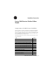
FactoryTalk Historian Machine Edition Module Topic See Page Connect the Module to the Ethernet Network 16 Apply Chassis Power 17 Check Power Supply and Module Status 17 LED Indicator Information 18 Four-character LED Display 19 Application Status 21 Port (Ethernet) LED Information 23 Where to Find Information on Configuring the Module 23 How to Upgrade and Reinstall the Firmware 22 Specifications 24 Publication 1756-IN611A-EN-P - February 2010
FactoryTalk Historian Machine Edition Module 3 I Important User Information Solid state equipment has operational characteristics differing from those of electromechanical equipment. Safety Guidelines for the Application, Installation and Maintenance of Solid State Controls (Publication SGI-1.1 available from your local Rockwell Automation sales office or online at http://www.ab.com/manuals/gi) describes some important differences between solid state equipment and hard-wired electromechanical devices.
FactoryTalk Historian Machine Edition Module Important User Information Burn Hazard Labels may be located on or inside the equipment (e.g., drive or motor) to alert people that surfaces may have dangerous temperatures. Environment and Enclosure Information Attention This equipment is intended for use in a Pollution Degree 2 industrial environment in overvoltage Category II applications (as defined in IEC publication 60664-1) at altitudes up to 2000 meters without derating.
FactoryTalk Historian Machine Edition Module 5 Prevent Electrostatic Discharge Information Attention This equipment is sensitive to electrostatic discharge, which can cause internal damage and affect normal operation. Follow these guidelines when you handle this equipment: • Touch a grounded object to discharge potential static. • Wear an approved grounding wriststrap. • Do not touch connectors or pins on component boards. • Do not touch circuit components inside the equipment.
FactoryTalk Historian Machine Edition Module Removal and Insertion Under Power (RIUP) Capability WARNING When you insert or remove the module while backplane power is on, an electrical arc can occur. This could cause an explosion in hazardous location installations. Be sure that power is removed or the area is nonhazardous before proceeding. Repeated electrical arcing causes excessive wear to contacts on both the module and its mating connector.
FactoryTalk Historian Machine Edition Module 7 The following information applies when operating this equipment in hazardous locations: WARNING EXPLOSION HAZARD Informations sur l’utilisation de cet équipement en environnements dangereux: AVERTISSEMENT • Do not disconnect equipment unless power has been removed or the area is known to be nonhazardous. • Do not disconnect connections to this equipment unless power has been removed or the area is known to be nonhazardous.
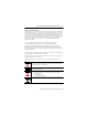
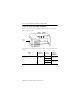
FactoryTalk Historian Machine Edition Module Identify FactoryTalk Historian ME Module Components Use the following figures to identify the external features of the FactoryTalk Historian ME Module. FactoryTalk Historian ME Module Front View In the following figure, the FactoryTalk Historian ME Module is shown from the front view with the four-character LED display, LED indicators (BAT, STS, OK), and Ethernet port locations identified.
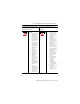
FactoryTalk Historian Machine Edition Module 9 FactoryTalk Historian ME Module Side View In the following figure, the FactoryTalk Historian ME Module is shown from the side view with the backplane and compact flash card slot location identified. IMPORTANT All data on the compact flash card is locked to Historian ME modules. It cannot be read by any other device.
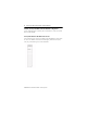
FactoryTalk Historian Machine Edition Module Prepare the Chassis for Module Installation Before you install the module, you must install and connect a ControlLogix chassis and power supply. Power Supply For information on installing these products, refer to the publications listed below. Chassis Type Chassis Installation Series B: 1756-A4, -A7, -A10, -A13, -A17 Pub. No. 1756-IN080 Power Supply Power Supply Installation 1756-PA72/B Pub. No. 1756-5.
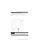
FactoryTalk Historian Machine Edition Module 11 Determine Module Slot Location You can install the module in any slot in the ControlLogix chassis. You can have a maximum of two 1756-HIST modules in the same chassis. The figure below shows chassis slot numbering in a 4-slot chassis. Slot 0 is the first slot and is always the leftmost slot in the rack (the first slot to the right of the power supply).
FactoryTalk Historian Machine Edition Module Install the Module in the Chassis 1 Align the circuit board with the top and bottom guides in the chassis. Circuit Board 2 Slide the module into the chassis. Make sure the module backplane connector properly connects to the chassis backplane. 3 The module is properly installed when it is flush with the power supply or other installed modules.
FactoryTalk Historian Machine Edition Module 13 Remove or Replace the Module (when applicable) 1 Push on the upper and lower module tabs to disengage them. 2 Slide the module out of the chassis. IMPORTANT If you are replacing an existing module with an identical one, and you want to resume identical system operation, you must install the new module in the same slot.
FactoryTalk Historian Machine Edition Module Install or Remove the Module Under Power This module is designed to be installed or removed while chassis power is applied. Rockwell Automation recommends that you stop all data collection services before you remove the module. WARNING When you insert or remove a module while backplane power is on, an electrical arc may occur.
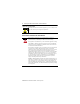
FactoryTalk Historian Machine Edition Module 15 Connect the Module to the Ethernet Network WARNING If you connect or disconnect the Ethernet cable with power applied to this module or any device on the network, an electrical arc can occur. This could cause an explosion in hazardous location installations. Be sure that power is removed or the area is nonhazardous before proceeding. Attach the RJ45 connector the Ethernet port on the front of the module as shown.
FactoryTalk Historian Machine Edition Module Apply Chassis Power Check Power Supply and Module Status Check the LED indicators and four-character LED display to determine if the power supply and module are operating properly. Note that it can take up to four to five minutes for the module to become fully operational once power is applied.
FactoryTalk Historian Machine Edition Module 17 LED Indicator Information There are two LED indicators on the front panel of the FactoryTalk Historian ME Module: the three status LED lights and the four-character LED display. These LED indicators determine if the power supply and module are operating properly. They are described in the following sections.
FactoryTalk Historian Machine Edition Module LED light On power-up Status Description OK Green Module status. Single bi-color red/green LED. Red indicates a major fault has occurred in the module. Green indicates the module is operating normally. Four-character LED Display The four-character LED display provides system status in a static and/or scrolling string on the front panel of the FactoryTalk Historian ME Module.
FactoryTalk Historian Machine Edition Module 19 Process or component Four-character display Description Ethernet port LAN OK Displays “LAN OK” if the Ethernet port is configured and the IP address is acquired properly, followed by the IP address. Ethernet port LAN LOST Displays “LAN LOST” for several seconds if the Ethernet port fails to acquire the IP address. After “LAN LOST” appears, the MAC address will be displayed. Application subsystems Configuration status: not configured, no points.
FactoryTalk Historian Machine Edition Module Application Status The Application Status is composed of four application subsystems, as described in the following table. Note: If more than one of the four statuses exist, then they are displayed one after another with a two second duration between each message. Application Subsystem Configuration status Status A. Not configured B.
FactoryTalk Historian Machine Edition Module 21 Application Subsystem Data collection status Status A. collect ok B. collect stopped Data transfer status A. upload ok B. upload stopped Data storage status A. storage critical B. storage full Description If Data Collection is active and properly configured, then the “collect ok.” If Data Collection is configured but not active, then the “collect stopped” status is displayed.
FactoryTalk Historian Machine Edition Module Port (Ethernet) LED Information The Port (Ethernet) LED on the 10/100 BASET connector supports IEEE 802.3, has a green LED for link activity, and an amber LED for 10/100 link speed indication. Where to Find Information on Configuring the Module To configure your module, refer to the FactoryTalk Historian ME User’s Guide, publication number 1756-UM611A, available on the FactoryTalk Historian ME Installation CD and online at www.rockwellautomation.
FactoryTalk Historian Machine Edition Module 23 – The firmware version number, which is listed on the FactoryTalk Historian ME Module’s home page. IMPORTANT Any kind of firmware upgrade or reinstall will clear out all logs. A firmware upgrade will preseve archived data and application configuration information, but a reinstall will clear out all application configuration information and archived data. If you want to save your settings, therefore, download and back up your configuration and logs.
FactoryTalk Historian Machine Edition Module Specifications Cat. No.
FactoryTalk Historian Machine Edition Module 25 Cat. No. 1756-HIST1G | 1756-HIST2G All supply voltages and/or current ratings. 5.1 V DC @ 800 mA 24 V DC @ 3 mA Isolation Voltage 30V (continuous), Basic Insulation Type. Type tested at 500V AC for 60 s, Ethernet to System Wire Size Ethernet connections: RJ45 connector according to IEC 60603-7, 2 or 4 pair Category 5e minimum cable according to TIA 568-B.
Rockwell Automation Support Rockwell Automation provides technical information on the web to assist you in using its products. At http://support.rockwellautomation.com, you can find technical manuals, a knowledge base of FAQs, technical and application notes, sample code and links to software service packs, and a MySupport feature that you can customize to make the best use of these tools.