Installation Instructions EtherNet/IP Web Server Module Catalog Number 1756-EWEB Use this manual as a guide to install the EtherNet/IP® Web Server Module. Note that this document covers hardware installation and some configuration procedures to get you started. Refer to the EtherNet/IP Web Server Module User Manual, publication number ENET-UM527, for more detailed configuration information. The following table lists the contents of this document and where to find specific information.
EtherNet/IP Web Server Module Important User Information Solid state equipment has operational characteristics differing from those of electromechanical equipment. Safety Guidelines for the Application, Installation and Maintenance of Solid State Controls (Publication SGI-1.1 available from your local Rockwell Automation sales office or online at http://www.ab.com/manuals/gi) describes some important differences between solid state equipment and hard-wired electromechanical devices.
EtherNet/IP Web Server Module 3 Environment and Enclosure This equipment is intended for use in a Pollution Degree 2 industrial environment, in overvoltage Category II applications (as defined in IEC publication 60664-1), at altitudes up to 2000 meters without derating. This equipment is considered Group 1, Class A industrial equipment according to IEC/CISPR Publication 11.
EtherNet/IP Web Server Module Preventing Electrostatic Discharge ATTENTION This equipment is sensitive to electrostatic discharge, which can cause internal damage and affect normal operation. Follow these guidelines when you handle this equipment: • Touch a grounded object to discharge potential static. • Wear an approved grounding wriststrap. • Do not touch connectors or pins on component boards. • Do not touch circuit components inside the equipment. • If available, use a static-safe work station.
EtherNet/IP Web Server Module 5 Compliance with the Essential Health and Safety Requirements has been assured by compliance with EN 50021. IMPORTANT When using this equipment, consider the following: • This equipment is not resistant to sunlight or other sources of UV radiation. • The secondary of a current transformer shall not be open-circuited when applied in Class I, Zone 2 environments.
EtherNet/IP Web Server Module investigation by the local Authority Having Jurisdiction at the time of installation. WARNING EXPLOSION HAZARD • Do not disconnect equipment unless power has been removed or the area is known to be nonhazardous. • Do not disconnect connections to this equipment unless power has been removed or the area is known to be nonhazardous.
EtherNet/IP Web Server Module 7 du système. Les combinaisons d'équipements dans le système sont sujettes à inspection par les autorités locales qualifiées au moment de l'installation. AVERTISSEMENT RISQUE D’EXPLOSION • Couper le courant ou s’assurer que l’environnement est classé non dangereux avant de débrancher l’équipement. • Couper le courant ou s’assurer que l’environnement est classé non dangereux avant de débrancher les connecteurs.
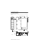
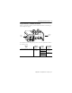
EtherNet/IP Web Server Module Identify Module Components Use the following figure to identify the external features of the 1756-EWEB module.
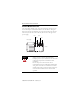
EtherNet/IP Web Server Module 9 Prepare the Chassis for Module Installation Before you install the module, you must install and connect a ControlLogixTM chassis and power supply. 1756-A4 Chassis Power Supply 20805-M For information on installing these products, refer to the publications listed in the following table. Chassis Type Chassis Installation Power Supply Power Supply Installation Series B: 1756-A4, -A7, -A10, -A13 Pub. No. 1756-IN080 1756-PA72/B Pub. No. 1756-5.
EtherNet/IP Web Server Module Determine Module Slot Location You can install the module in any slot in the ControlLogix chassis. You can also install multiple 1756-EWEB modules in the same chassis. The figure below shows chassis slot numbering in a 4-slot chassis. Slot 0 is the first slot and is always the left-most slot in the rack (the first slot to the right of the power supply).
EtherNet/IP Web Server Module 11 Install the Module 1 Align the circuit board with top and bottom guides in the chassis. Circuit Board 31275-M 2 Slide the module into the chassis. Make sure the module backplane connector properly connects to the chassis backplane. 3 The module is properly installed when it is flush with the power supply or other installed modules.
EtherNet/IP Web Server Module Removing or Replacing the Module (when applicable) 1 Push on upper and lower module tabs to disengage them. 31277-M 31278-M 2 Slide module out of chassis. IMPORTANT If you are replacing an existing module with an identical one, and you want to resume identical system operation, you must install the new module in the same slot.
EtherNet/IP Web Server Module 13 Installing or Removing the Module Under Power This module is designed to be installed or removed while chassis power is applied. WARNING When you insert or remove the module while backplane power is on, an electrical arc can occur. This could cause an explosion in hazardous location installations. Be sure that power is removed or the area is nonhazardous before proceeding.
EtherNet/IP Web Server Module Connect the Module to the EtherNet/IP Network WARNING If you connect or disconnect the communications cable with power applied to this module or any device on the network, an electrical arc can occur. This could cause an explosion in hazardous location installations. Attach the RJ45 connector to the EtherNet/IP port on the bottom of the module as shown below: RJ-45 EtherNet/IP connector Connect the cable here.
EtherNet/IP Web Server Module 15 IMPORTANT We recommend connecting the module to the network via a 100MB EtherNet/IP switch, which will reduce collisions and lost packets and increase network bandwidth.
EtherNet/IP Web Server Module Check Power Supply and Module Status Check the LED indicators and alphanumeric display to determine if the power supply and module are operating properly. Web + Alphanumeric Display LINK NET OK LINK Power Supply indicator is GREEN. NET OK indicator is red during self-test, then green. 31281-M The alphanumeric display should cycle through the following states: “TEST PASS - OK - REV x.x,” where “x.x” is the module’s firmware revision.
EtherNet/IP Web Server Module 17 Obtain an IP Address By default, the web server module is DHCP enabled. If you connect the web server module to a network that has a DHCP server, that server will assign a dynamic IP address to the web server module and the four-digit display on the front of the web server module will display each of the four numbers of the IP address.
EtherNet/IP Web Server Module Log Into the Module Many of the features of the web server module require you to log in with appropriate access. If you select a feature, such as New Data View, the web server module prompts you to enter your user name and password. The default user name is “Administrator” with no password (leave the Password field blank). Default Access: User Name: Administrator (not case sensitive) Password: (leave blank, no password) You can set up as many as 25 user accounts.
EtherNet/IP Web Server Module 19 Confirm the Network Configuration On the Administrator Settings → Device Configuration → Network Configuration page, you can verify the IP address and other network settings. For more information, see the EtherNet/IP Web Server Module User Manual, publication ENET-UM527.
EtherNet/IP Web Server Module Create a Data View Before you can create a data view in the web server, the tags you want to view must exist in the controller that is local (in the same chassis) to the web server module. The tags in the controller must be controller-scoped. For example, create: TEST type DINT controller-scope value 123 To create a create a data view, you need Administrator or Write access. You create a data view from the Data Views → New Data View page. 1.
EtherNet/IP Web Server Module 21 3. Click on the Add button to add the tag to the data view Continue adding as many tags as you want to configure. 4. Click Create View. 5. From the Data Views → Data View page, select the data view you just created. 6. Click on the filename link to view the tags in this data view. 7. Type the new value in the box next to the tag and click the Update button. This changes the value in the controller.
EtherNet/IP Web Server Module Note: To change a data value, you need Administrator or Write access. For more information, see the EtherNet/IP Web Server Module User Manual, publication ENET-UM527A. Configure Email You configure the SMTP server that manages email on the Administrative Settings → Device Configuration → Network Configuration page. You can enter and send an email from the Send an Email link on the web server module.
EtherNet/IP Web Server Module 23 Configure the Time Server You select the method the web server module uses to maintain an accurate date and time stamp on the Administrative Settings → Server Management → Time Settings page. This makes sure that files you save to the web server module have accurate date and time stamps. Select: • SNTP Time Server to get the date and time from an SNTP server on the network. • Query Controller to get the date and time from the local controller.
EtherNet/IP Web Server Module Enable/Disable Other Services You can enable other services from the Administrative Settings → Device Configuration → Device Services page. Select the services you want to use.
EtherNet/IP Web Server Module 25 Troubleshooting the Module If the alphanumeric display and LED indicators do not sequence through the expected states refer to the following troubleshooting tables. The three bi-color (red/green) LED status indicators on the 1756-EWEB module provide diagnostic information about the module and its connections to the network.
EtherNet/IP Web Server Module Link Status Indicator The Link Status LED provides the following information: State Status Description Off No data transmission Module is not ready to communicate. Green Ready Module is ready to communicate. Flashing Green Data transmission in progress Module is communicating over the network. OK Status Indicator The OK Status LED provides the following module information: State Status Description Off No Power Module does not have 24V DC power.
EtherNet/IP Web Server Module 27 Specifications Specification: Value: Module Location Any slot in the ControlLogix chassis Maximum Backplane Current Load 700mA @ 5.1V DC 3mA @ 24V DC from I/O chassis backplane Power Dissipation 3.
EtherNet/IP Web Server Module Specification: Value: ESD Immunity IEC 61000-4-2: 6kV contact discharges 8kV air discharges Radiated RF Immunity IEC 61000-4-3: 10V/m with 1kHz sine-wave 80%AM from 30MHz to 1000MHz 10V/m with 200Hz 50% Pulse 100%AM at 900Mhz EFT/B Immunity IEC 61000-4-4: ±2kV at 5kHz on communications ports Surge Transient Immunity ±2kV line-earth(CM) on shielded ports ±2kV line-earth unshielded ports Conducted RF Immunity IEC 61000-4-6: 10Vrms with 1kHz sine-wave 80%AM from 150k
EtherNet/IP Web Server Module 29 Specification: Value: User Manual Publication ENET-UM527A Certifications (when product is marked) UL: UL Listed Industrial Control Equipment CSA: CSA Certified Process Control Equipment CSA Certified Process Control Equipment for Class I, Division 2 Group A,B,C,D Hazardous Locations CE2: European Union 89/336/EEC EMC Directive, compliant with: EN 50081-2; Industrial Emissions EN 61326; Meas./Control/Lab.
Rockwell Automation Support Rockwell Automation provides technical information on the web to assist you in using our products. At http://support.rockwellautomation.com, you can find technical manuals, a knowledge base of FAQs, technical and application notes, sample code and links to software service packs, and a MySupport feature that you can customize to make the best use of these tools.