
User Manual

70 Rockwell Automation Publication ENET-IN002F-EN-P - January 2014
Chapter 3 Install a 1769 EtherNet/IP Adapter
7. Attach an end cap terminator (d) to the last I/O module in the system by
using the tongue-and-groove slots as before.
8. Lock the end-cap bus terminator (e).
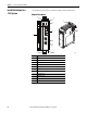
Mount the Adapter and I/O Modules
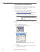
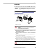
Minimum Spacing
Maintain spacing from enclosure walls, wireways, and adjacent equipment.
Allow 50 mm (2 in.) of space on all sides for adequate ventilation, as shown.
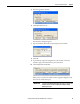
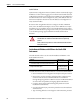
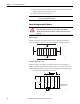
Mount the Adapter with Screws
Mount the adapter or module to a panel by using two screws per adapter or
module. Use M4 or #8 panhead screws. Mounting screws are required on every
module. This figure illustrates panel mounting using the dimensional template.
IMPORTANT
A 1769-ECR or 1769-ECL right or left end cap must be used to terminate the
end of the serial communication bus.
ATTENTION: During panel or DIN rail mounting of all devices, be sure that all
debris (metal chips, wire strands) is kept from falling into the adapter or
modules. Debris that falls into the adapter or modules could cause damage on
power up.
1769 I/O
1769 I/O
1769 I/O
End Cap or Cable
42124
1769 I/O
1769 Power Supply
Side Side
Bottom
Top
1769 I/O
1769 I/O
1769-AENTR
For more than 1 module: Number of modules x 35 mm (1.38 in.)
28.5
(1.12)
35
(1.38)
132
(5.197)
(4.826
+0.008)
122.6
+0.2
1769-AENTR
1769 Power Supply
1769 I/O
Right End Cap
mm (in.)
Hole spacing tolerance:
±0.4 mm (0.016 in.)
42121
(1.38)
35
70
(2.76)
(1.58)
40
35
(1.38)
1769 I/O