Installation Instructions EtherNet/IP Modules Catalog Numbers 1756-ENBT, 1756-EN2F, 1756-EN2T, 1756-EN2TR, 1756-EN2TXT, 1756-EN2TRXT, 1756-EN2TSC, 1756-EN3TR, 1756-EWEB, 1768-ENBT, 1768-EWEB, 1769-AENTR
Important User Information Read this document and the documents listed in the additional resources section about installation, configuration, and operation of this equipment before you install, configure, operate, or maintain this product. Users are required to familiarize themselves with installation and wiring instructions in addition to requirements of all applicable codes, laws, and standards.
Summary of Changes This manual contains new and updated information. Changes throughout this revision are marked by change bars, as shown to the right of this paragraph. New and Updated Information This table contains the changes made in this revision.
Summary of Changes Notes: 4 Rockwell Automation Publication ENET-IN002F-EN-P - January 2014
Table of Contents Preface Studio 5000 Environment . . . . . . . . . . . . . . . . . . . . . . . . . . . . . . . . . . . . . . . . . . 9 Additional Resources . . . . . . . . . . . . . . . . . . . . . . . . . . . . . . . . . . . . . . . . . . . . . 10 Chapter 1 Install a 1756 EtherNet/IP Communication Module Installation Summary. . . . . . . . . . . . . . . . . . . . . . . . . . . . . . . . . . . . . . . . . . . . . Grounding Considerations . . . . . . . . . . . . . . . . . . . . . . . . . . . . . . . . .
Table of Contents Chapter 3 Install a 1769 EtherNet/IP Adapter System Configuration . . . . . . . . . . . . . . . . . . . . . . . . . . . . . . . . . . . . . . . . . . . . Example Configurations. . . . . . . . . . . . . . . . . . . . . . . . . . . . . . . . . . . . . . . Installation Summary . . . . . . . . . . . . . . . . . . . . . . . . . . . . . . . . . . . . . . . . . . . . . Grounding Considerations . . . . . . . . . . . . . . . . . . . . . . . . . . . . . . . . . . . . Set the Network IP Address . .
Table of Contents Appendix C 1769 EtherNet/IP Adapter Status Indicators . . . . . . . . . . . . . . . . . . . . . . . . . . . . . . . . . . . . . . . . . . . . . . . . . . . . . . . . . . . . . . . . . 95 Appendix D Fiber Cable and LC Connector Specifications . . . . . . . . . . . . . . . . . . . . . . . . . . . . . . . . . . . . . . . . . . . . . . . . . . . . 97 Index . . . . . . . . . . . . . . . . . . . . . . . . . . . . . . . . . . . . . . . . . . . . . . . . . . . . . . . . . . . . . . . . .
Table of Contents 8 Rockwell Automation Publication ENET-IN002F-EN-P - January 2014
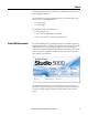
Preface This manual describes how to install and start up EtherNet/IP module systems with Logix5000 controllers.
Preface Additional Resources For more information on the products described in this publication, use these resources. Resource Description Ethernet Design Considerations Reference Manual, publication ENET-RM002 Provides details about how to use EtherNet/IP communication modules with Logix5000 controllers and communicate with other devices on the EtherNet/IP network.
Chapter 1 Install a 1756 EtherNet/IP Communication Module Topic Page Installation Summary 14 Determine Module Slot Location 14 Set the Network IP Address on a Module 15 Install the Module 25 Wire the Module 26 Download the Add-on Profile 29 Connect to the Module via the USB Port 30 Download the Firmware 31 Apply Chassis Power and Check Status Indicators 32 Install or Remove the Module Under Power 33 ATTENTION: Environment and Enclosure This equipment is intended for use in a Polluti
Chapter 1 Install a 1756 EtherNet/IP Communication Module North American Hazardous Location Approval The following information applies when operating this equipment in hazardous locations. Informations sur l’utilisation de cet équipement en environnements dangereux. Products marked "CL I, DIV 2, GP A, B, C, D" are suitable for use in Class I Division 2 Groups A, B, C, D, Hazardous Locations and nonhazardous locations only.
Install a 1756 EtherNet/IP Communication Module Chapter 1 European Hazardous Location Approval The following applies when the product bears the Ex Marking.
Chapter 1 Install a 1756 EtherNet/IP Communication Module Follow these steps to install a communication module in a 1756 ControlLogix chassis. Installation Summary 1. Set the Network IP Address on a Module. 2. Determine Module Slot Location. 3. Install the Module. 4. Connect the Module to an EtherNet/IP Network via an RJ45 Connection. or Connect the Module to an EtherNet/IP Network via a Fiber Connector. 5. Download the Add-on Profile. 6. Connect to the Module via the USB Port. 7. Download the Firmware.
Install a 1756 EtherNet/IP Communication Module Set the Network IP Address on a Module Chapter 1 To operate an EtherNet/IP communication module on an EtherNet/IP network, you must set a network IP address. The IP address uniquely identifies the module. The IP address is in the form xxx.xxx.xxx.xxx where each xxx is a number from 000…254. There are some reserved values that you cannot use as the first octet in the address. These numbers are examples of values you cannot use: • 001.xxx.xxx.xxx • 127.xxx.
Chapter 1 Install a 1756 EtherNet/IP Communication Module Figure 1 - How Your Module’s IP Address Is Set Module Powerup No Is DHCP or BOOTP enabled? No Module uses IP address stored in nonvolatile memory. Switches set from 001…254? Yes Yes Module requests address from DHCP/ BOOTP server. Module has an IP address. If you need to reset your module’s settings to its factory default settings during normal module operation, see Reset the Module IP Address to a Factory Default Value on page 25.
Install a 1756 EtherNet/IP Communication Module Chapter 1 Set the Network IP Address with the Rotary Switches This graphic shows the rotary switches on a 1756 EtherNet/IP communication module. Depending on the module, the switches are on the top or the side of the module. Front of Module 32454 Rotary Switches At powerup, the module reads the rotary switches to determine if they are set to a valid number for the last portion of the IP address, that is, if the numbers are in the range from 001…254.
Chapter 1 Install a 1756 EtherNet/IP Communication Module Set the Network IP Address with the BOOTP/DHCP Server The BOOTP/DHCP server is a standalone server you can use to set an IP address. When used, the BOOTP/DHCP server sets an IP address and other Transport Control Protocol (TCP) parameters. You can use the BOOTP/DHCP server to set the module’s IP address if one of these conditions exists at powerup: • The module’s rotary switches are not set to a valid number and the module is BOOTP/DHCP enabled.
Install a 1756 EtherNet/IP Communication Module Chapter 1 3. Type the Subnet Mask of the network. The Gateway address, Primary and/or Secondary DNS address, and Domain Name fields are optional. 4. Click OK. The Request History panel appears with the hardware addresses of all modules issuing BOOTP requests. 5. Select the appropriate module. 6. Click Add to Relation List. The New Entry dialog box appears. 7. Type an IP Address, Hostname, and Description for the module. 8. Click OK.
Chapter 1 Install a 1756 EtherNet/IP Communication Module 9. To permanently assign this configuration to the module, wait for the module to appear in the Relation List panel and select it. 10. Click Disable BOOTP/DHCP. When power is recycled, the module uses the assigned configuration and does not issue a BOOTP request. IMPORTANT If you do not click Disable BOOTP/DHCP, on a power cycle, the host controller clears the current IP configuration and begins sending BOOTP requests again.
Install a 1756 EtherNet/IP Communication Module Chapter 1 Set the Network IP Address with RSLinx Software or the Studio 5000 Environment This table describes when to set the network IP address with RSLinx software or the Studio 5000 environment. Conditions Software to Use Page • A BOOTP server is not available. • The EtherNet/IP communication module is connected to another NetLinx network.
Chapter 1 Install a 1756 EtherNet/IP Communication Module Set the Network IP Address with RSLinx Software Follow these steps to use RSLinx software to set the communication module’s IP address. 1. From the Communications menu, choose RSWho. The RSWho dialog box appears. 2. Navigate to the Ethernet network. 3. Right-click the EtherNet/IP module and choose Module Configuration. The Module Configuration dialog box appears. 4. Click the Port Configuration tab. 5.
Install a 1756 EtherNet/IP Communication Module • • • • • • • Chapter 1 In the IP Address field, type the IP address. In the Network Mask field, type the network mask address. In the Gateway Address field, type the gateway address. In the Primary Name Server field, type the IP address. In the Secondary Name Server field, type the IP address. In the Domain Name field, type the domain name. In the Host Name field, type the host name. 7. Configure the port settings.
Chapter 1 Install a 1756 EtherNet/IP Communication Module Set the Network IP Address with the Studio 5000 Environment Follow these steps to use the Studio 5000 environment to set the communication module’s IP address. 1. In the Controller Organizer, right-click the EtherNet/IP module and choose Properties. The Module Properties dialog box appears. 2. Click the Port Configuration tab. 3. In the IP Address field, type the IP address. 4. In the other fields, type the other network parameters, if needed.
Install a 1756 EtherNet/IP Communication Module Chapter 1 Reset the Module IP Address to a Factory Default Value You can reset the module’s IP address to its factory default value with the following methods: • If the module has rotary switches, set the switches to 888 and cycle power. • If the module does not have rotary switches, use a MSG instruction to the reset the IP address.
Chapter 1 Install a 1756 EtherNet/IP Communication Module 7. Align the circuit board with top and bottom guides in the chassis. 32455 8. Slide the module into the chassis. Make sure the module backplane connector properly connects to the chassis backplane. Note that the module is properly installed when it is flush with the power supply or other installed modules. Wire the Module Use the following information to wire the module.
Install a 1756 EtherNet/IP Communication Module • • • • • Chapter 1 1756-EN2TR - ControlLogix EtherNet/IP 2-port module 1756-EN2TRXT- ControlLogix-XT EtherNet/IP module 1756-EN2TXT - ControlLogix-XT EtherNet/IP module 1756-EN3TR - ControlLogix EtherNet/IP 2-port module 1756-EWEB - ControlLogix EtherNet/IP Web Server module Wire the RJ45 connector as shown.
Chapter 1 Install a 1756 EtherNet/IP Communication Module Connect the Module to an EtherNet/IP Network via a Fiber Connector The 1756-EN2F ControlLogix EtherNet/IP module uses a fiber connector to connect to an EtherNet/IP network. Attach the LC2 multi-mode fiber cable to the Ethernet port on the bottom of the module as shown. ATTENTION: Do not look directly into the optical port. Under certain conditions, viewing the optical port may expose the eye to hazard.
Install a 1756 EtherNet/IP Communication Module Download the Add-on Profile Chapter 1 If a module has a later firmware revision for the communication module than recognized in the most current version of the Logix Designer application, you need to download the Add-on Profile (AOP) for the communication module so it can be recognized in the Controller Organizer. Complete these steps to download and install an AOP. 1. Go to the Rockwell Automation Web site at http://www.rockwellautomation.com/. 2.
Chapter 1 Install a 1756 EtherNet/IP Communication Module 9. When the downloaded is complete, click Close. 10. Locate the downloaded .zip file and extract it to a temporary directory. 11. Shut down any instances of the Logix Designer application that are currently running. 12. In the temporary directory, double-click the MPSetup.exe file and follow the onscreen instructions to install the AOP.
Install a 1756 EtherNet/IP Communication Module Download the Firmware Chapter 1 Complete these steps to download and install the firmware. 1. Go to the Rockwell Automation Web site at http://www.rockwellautomation.com/. 2. From the Support tab, product Product Compatibility & Download Center. 3. On the Get Downloads tab, click Find Product Downloads. 4. Enter your search criteria and click Go. 5. Select the module from the list then click the Find Downloads button at the bottom of the Selections tab. 6.
Chapter 1 Install a 1756 EtherNet/IP Communication Module Digitally Signed Firmware Digitally signed firmware provides an extra level of integrity at the firmware level. The following modules are compatible with signed firmware, depending on the firmware version: • 1756-EN2F • 1756-EN2TRXT • 1756-EN2T • 1756-EN2TXT • 1756-EN2TSC • 1756-EN3TR • 1756-EN2TR IMPORTANT Installing signed firmware into your product will make it incompatible with some versions of firmware.
Install a 1756 EtherNet/IP Communication Module Chapter 1 2. Check the power supply and module status indicators and alphanumeric display to determine that the power supply and module are operating properly. The alphanumeric display should cycle through the following states: TEST - PASS - OK - REV x.x, where x.x is the module’s firmware revision. The display then alternates between OK and port link status for both ports.
Chapter 1 Install a 1756 EtherNet/IP Communication Module Follow these steps to remove or replace the module. 1. Push on the upper and lower module tabs to disengage them. 32460 2. Slide the module out of the chassis. 32461 IMPORTANT 34 If you want to replace an existing module with an identical one, and you want to resume identical system operation, you must install the new module in the same slot and assign the same network configuration.
Chapter 2 Install a 1768 EtherNet/IP Communication Module Topic Page Installation Summary 37 Set the Network IP Address 38 Install the Module 46 Wire the Module 48 Download the Add-on Profile 49 Download the Firmware 50 Apply Chassis Power and Check Status Indicators 51 Remove the Module 52 ATTENTION: Environment and Enclosure This equipment is intended for use in a Pollution Degree 2 industrial environment, in overvoltage Category II applications (as defined in IEC 60664-1), at altitud
Chapter 2 Install a 1768 EtherNet/IP Communication Module North American Hazardous Location Approval The following information applies when operating this equipment in hazardous locations. Informations sur l’utilisation de cet équipement en environnements dangereux. Products marked "CL I, DIV 2, GP A, B, C, D" are suitable for use in Class I Division 2 Groups A, B, C, D, Hazardous Locations and nonhazardous locations only.
Install a 1768 EtherNet/IP Communication Module Chapter 2 European Hazardous Location Approval The following applies when the product bears the Ex Marking.
Chapter 2 Install a 1768 EtherNet/IP Communication Module Grounding Considerations ATTENTION: This product is grounded through the DIN rail to chassis ground. Use zinc-plated yellow-chromate steel DIN rail to assure proper grounding. The use of other DIN rail materials (for example, aluminum or plastic) that can corrode, oxidize, or are poor conductors, can result in improper or intermittent grounding. Secure DIN rail to mounting surface approximately every 200 mm (7.87 in.
Install a 1768 EtherNet/IP Communication Module Chapter 2 This graphic shows the process used to set your module’s IP address. Figure 2 - How Your Module’s IP Address is Set Module Powerup No Adapter uses IP address stored in nonvolatile memory. Is DHCP or BOOTP enabled? Yes Module requests address from DHCP/ BOOTP server. Module has an IP address.
Chapter 2 Install a 1768 EtherNet/IP Communication Module Set the Network IP Address with a BOOTP/DHCP Server The BOOTP/DHCP server is a standalone server you can use to set an IP address. When used, the BOOTP/DHCP server sets an IP address and other Transport Control Protocol (TCP) parameters. Access the BOOTP/DHCP server from one of these locations: • Programs > Rockwell Software > BOOTP-DHCP Server If you have not installed the server, you can download and install it from http://www.ab.
Install a 1768 EtherNet/IP Communication Module Chapter 2 5. Select the appropriate module. 6. Click Add to Relation List. The New Entry dialog box appears. 7. Type an IP Address, Hostname, and Description for the module. 8. Click OK. 9. To permanently assign this configuration to the module, wait for the module to appear in the Relation List panel and select it. 10. Click Disable BOOTP/DHCP. When power is recycled, the module uses the assigned configuration and does not issue a BOOTP request.
Chapter 2 Install a 1768 EtherNet/IP Communication Module Use DHCP Software Dynamic Host Configuration Protocol (DHCP) software automatically assigns IP addresses to client stations logging onto a TCP/IP network. DHCP is based on BOOTP and maintains some backward compatibility. The main difference is that BOOTP allows for manual configuration (static), while DHCP allows for both static and dynamic allocation of network addresses and configurations to newly attached modules.
Install a 1768 EtherNet/IP Communication Module Chapter 2 If you use the Rockwell Automation BOOTP or DHCP server in an uplinked subnet where an enterprise DHCP server exists, a module may get an address from the enterprise server before the Rockwell Automation utility even sees the module. You might have to disconnect from the uplink to set the address and configure the module to retain its static address before reconnecting to the uplink.
Chapter 2 Install a 1768 EtherNet/IP Communication Module 5. For Network Configuration Type, click Static to permanently assign this configuration to the port. IMPORTANT If you click Dynamic, on a power cycle, the controller clears the current IP configuration and resumes sending BOOTP requests. 6. Type this information in the appropriate fields: • In the IP Address field, type the IP address. • In the Network Mask field, type the network mask address.
Install a 1768 EtherNet/IP Communication Module Chapter 2 Set the Network IP Address with the Studio 5000 Environment Follow these steps to use the Logix Designer application from the Studio 5000 environment to set the communication module’s IP address. 1. In the Controller Organizer, right-click the EtherNet/IP module and choose Properties. The Module Properties dialog box appears. 2. Click the Port Configuration tab. 3. In the IP Address field, type the IP address. 4.
Chapter 2 Install a 1768 EtherNet/IP Communication Module Reset the Module IP Address to a Factory Default Value You can reset the module’s IP address to its factory default value by sending a MSG instruction to the module. For more information on resetting the network IP address to its default value with a MSG instruction, see Knowledgebase Answer ID 55362, Reset module to factory defaults. You can access the article at http://rockwellautomation.custhelp.com/app/answers/list.
Install a 1768 EtherNet/IP Communication Module Chapter 2 Mount on a DIN Rail Follow these steps to install the module on a DIN rail. 1. Mount the DIN rail in a suitable location. ATTENTION: This product is grounded through the DIN rail to chassis ground. Use zinc-plated yellow-chromate steel DIN rail to assure proper grounding. The use of other DIN rail materials (for example, aluminum or plastic) that can corrode, oxidize, or are poor conductors, can result in improper or intermittent grounding.
Chapter 2 Install a 1768 EtherNet/IP Communication Module 5. Mount the 1768 power supply and additional 1768 modules to the left of the controller. 6. Close the DIN rail latches. 31599-M In this example, the 1768 EtherNet/IP communication module is installed in slot 1 and the 1768 CompactLogix controller is installed in slot 0. Wire the Module Use the following information to wire the module. Connect the Module to an EtherNet/IP Network via an RJ45 Connection Wire the RJ45 connector as shown.
Install a 1768 EtherNet/IP Communication Module Chapter 2 1. Attach the cable with the RJ45 connector to the Ethernet port on the bottom of the module as shown. 2. Attach the other end of the cable to the devices in your network.
Chapter 2 Install a 1768 EtherNet/IP Communication Module 6. Click the download graphic . The Available Downloads window opens. 7. From the bulleted list, choose the firmware name. The End User License Agreement opens. 8. Review the agreement and click I Agree. The Rockwell Automation Download Manager opens and the download begins. The location of the downloaded file is shown under the progress bar. 9. When the downloaded is complete, click Close. 10. Locate the downloaded .
Install a 1768 EtherNet/IP Communication Module 6. Click the download graphic Chapter 2 . The Available Downloads window opens. 7. From the bulleted list, choose the firmware name. The End User License Agreement opens. 8. Review the agreement and click I Agree. The Rockwell Automation Download Manager opens and the download begins. The location of the downloaded file is shown under the progress bar. 9. When the downloaded is complete, click Close. 10. Locate the downloaded .
Chapter 2 Install a 1768 EtherNet/IP Communication Module 2. Check the power supply (1) and module (2) status indicators and alphanumeric display to determine that the power supply and module are operating properly. 1 Remove the Module 2 Follow these steps to remove the communication module. IMPORTANT When you turn the CompactLogix power supply off, make sure you wait for all status indicators on the power supply and controller to turn off before disconnecting any part from the system.
Install a 1768 EtherNet/IP Communication Module Chapter 2 2. Open the DIN rail latches of the communication module and the module directly to the left of communication module. 3. Slide the communication module and other modules to the right. 4. Open the DIN rail latches of the controller.
Chapter 2 Install a 1768 EtherNet/IP Communication Module 5. Slide the controller and other modules away from the communication module. 6. Pull the communication module off the DIN rail.
Chapter 3 Install a 1769 EtherNet/IP Adapter Topic Page System Configuration 57 Installation Summary 59 Set the Network IP Address 59 Install the Adapter in a 1769 System 68 Wire the Adapter 72 Download the Add-on Profile 74 Download the Firmware 75 Enable the Web Pages 76 Remove or Replace the Adapter 77 ATTENTION: Environment and Enclosure This equipment is intended for use in a Pollution Degree 2 industrial environment, in overvoltage Category II applications (as defined in IEC 606
Chapter 3 Install a 1769 EtherNet/IP Adapter North American Hazardous Location Approval The following information applies when operating this equipment in hazardous locations. Informations sur l’utilisation de cet équipement en environnements dangereux. Products marked "CL I, DIV 2, GP A, B, C, D" are suitable for use in Class I Division 2 Groups A, B, C, D, Hazardous Locations and nonhazardous locations only.
Install a 1769 EtherNet/IP Adapter System Configuration Chapter 3 Follow these rules when planning your system configuration. • The adapter must be the first and left-most module in the system (the first module of Bank 1). Refer to page 58 for an example configuration. • The adapter can communicate with up to 30 modules in a system distributed across three I/O banks. • An end cap/terminator must be on the last I/O bank. • Each bank of I/O must have its own power supply.
Chapter 3 Install a 1769 EtherNet/IP Adapter Example Configurations 1769 I/O 1769 I/O 3 4 5 6 1769-CRRx 1769 I/O 2 1769 Power Supply 1 1769 I/O I/O Slot Number 1769 I/O Bank 1 1769 I/O 1769-AENTR The following illustrations show examples of two valid system setups.
Install a 1769 EtherNet/IP Adapter Installation Summary Chapter 3 Complete these steps to install an adapter in a 1769 CompactLogix system. 1. Set the Network IP Address. 2. Install the Adapter in a 1769 System. 3. Wire the Adapter. 4. Download the Add-on Profile. 5. Download the Firmware. - Optional 6. Remove or Replace the Adapter. - Optional Grounding Considerations ATTENTION: This product is grounded through the DIN rail to chassis ground.
Chapter 3 Install a 1769 EtherNet/IP Adapter You can use these tools to set the network Internet Protocol (IP) address on your 1769 EtherNet/IP adapter: • Bootstrap Protocol (BOOTP)/Dynamic Host Configuration Protocol (DHCP) server - available out-of box • RSLinx Classic software - only available for previously-configured adapters • Studio 5000 Logix Designer application, version 20.00.
Install a 1769 EtherNet/IP Adapter Chapter 3 These tools are used in this sequence to set the network IP address. 1. Set the Network IP Address with the Rotary Switches. 2. Set the Network IP Address with a BOOTP/DHCP Server. 3. Set the Network IP Address with RSLinx or the Studio 5000 Environment. Set the Network IP Address with the Rotary Switches This graphic shows the rotary switches on the front the adpater.
Chapter 3 Install a 1769 EtherNet/IP Adapter Set the Network IP Address with a BOOTP/DHCP Server The BOOTP/DHCP server is a standalone server you can use to set an IP address. When used, the BOOTP/DHCP server sets an IP address and other Transport Control Protocol (TCP) parameters. Access the BOOTP/DHCP server from one of these locations: • Programs > Rockwell Software > BOOTP-DHCP Server If you have not installed the server, you can download and install it from http://www.ab.com/networks/ethernet/bootp.
Install a 1769 EtherNet/IP Adapter Chapter 3 5. Select the appropriate module. 6. Click Add to Relation List. The New Entry dialog box appears. 7. Type an IP Address, Hostname, and Description for the module. 8. Click OK. 9. To permanently assign this configuration to the module, wait for the module to appear in the Relation List panel and select it. 10. Click Disable BOOTP/DHCP. When power is recycled, the module uses the assigned configuration and does not issue a BOOTP request.
Chapter 3 Install a 1769 EtherNet/IP Adapter Use DHCP Software Dynamic Host Configuration Protocol (DHCP) software automatically assigns IP addresses to client stations logging onto a TCP/IP network. DHCP is based on BOOTP and maintains some backward compatibility. The main difference is that BOOTP allows for manual configuration (static), while DHCP allows for both static and dynamic allocation of network addresses and configurations to newly attached modules.
Install a 1769 EtherNet/IP Adapter Chapter 3 If you use the Rockwell Automation BOOTP or DHCP server in an uplinked subnet where an enterprise DHCP server exists, a module can get an address from the enterprise server before the Rockwell Automation utility even sees the module. In this case, disconnect from the uplink to set the address and configure the module to retain its static address before reconnecting to the uplink.
Chapter 3 Install a 1769 EtherNet/IP Adapter 4. Click the Port Configuration tab. 5. For Network Configuration Type, click Static to permanently assign this configuration to the port. IMPORTANT If you click Dynamic, on a power cycle, the controller clears the current IP configuration and resumes sending BOOTP requests. 6. Type this information in the appropriate fields: • In the IP Address field, type the IP address. • In the Network Mask field, type the network mask address.
Install a 1769 EtherNet/IP Adapter Chapter 3 Set the Network IP Address with the Studio 5000 Environment Complete these steps to use the Logix Designer application to set the adapter’s IP address. 1. In the Controller Organizer, right-click the EtherNet/IP module and choose Properties. The Module Properties dialog box appears. 2. Click the Port Configuration tab. 3. In the IP Address field, type the IP address. 4. In the other fields, type the other network parameters, if needed. 5. Click Apply. 6.
Chapter 3 Install a 1769 EtherNet/IP Adapter Install the Adapter in a 1769 System Use the following information to install the adapter with the 1769 system.
Install a 1769 EtherNet/IP Adapter Chapter 3 System Assembly The adapter can be attached to adjacent 1769 modules before or after mounting. IMPORTANT The 1769-AENTR adapter must be used with one of the following Rockwell Automation power supply models: 1769-PA2, 1769-PB2, 1769-PA4, or 1769-PB4. For mounting instructions, see Mount the Adapter with Screws on page 70, or Mount on a DIN Rail on page 71. Follow these steps to assemble the Compact I/O™ system. a b c a e 1769- a a d 42126 1.
Chapter 3 Install a 1769 EtherNet/IP Adapter 7. Attach an end cap terminator (d) to the last I/O module in the system by using the tongue-and-groove slots as before. 8. Lock the end-cap bus terminator (e). A 1769-ECR or 1769-ECL right or left end cap must be used to terminate the end of the serial communication bus.
Install a 1769 EtherNet/IP Adapter Chapter 3 Mount to Module with Screws by Using the Modules as a Template The following procedure lets you use the assembled adapter and modules as a template for drilling holes in the panel. If you have sophisticated panel mounting equipment, you can use the dimensional template provided on page 70. Due to the module-mounting hole tolerance, it is important to follow this procedures. 1. On a clean work surface, assemble no more than three modules. 2.
Chapter 3 Install a 1769 EtherNet/IP Adapter Wire the Adapter Use the following information to wire the adapter. Ground the Adapter This product is intended to be mounted to a well-grounded mounting surface such as a metal panel. Additional grounding connections from the adapter’s mounting tabs or DIN rail (if used) are not required unless you cannot ground the mounting surface. Refer to Industrial Automation Wiring and Grounding Guidelines, publication 1770-4.1, for additional information.
Install a 1769 EtherNet/IP Adapter Chapter 3 Use the Module in a Device-level Ring (DLR) Network The module is configured by default to be used in a linear or star topology, or as a ring node in a DLR network. Follow these steps to use the module in a DLR network as a ring supervisor. 1. If you are using the unit as a ring supervisor, follow the procedures outlined in the online help that accompanies RSLinx or the Logix Designer application to enable the ring supervisor function with this software.
Chapter 3 Install a 1769 EtherNet/IP Adapter Download the Add-on Profile If a module has a later firmware revision for the communication module than recognized in the most current version of the Logix Designer application, you need to download the Add-on Profile (AOP) for the communication module so it can be recognized in the Controller Organizer. Complete these steps to download and install an AOP. 1. Go to the Rockwell Automation Web site at http://www.rockwellautomation.com/. 2.
Install a 1769 EtherNet/IP Adapter Chapter 3 9. When the downloaded is complete, click Close. 10. Locate the downloaded .zip file and extract it to a temporary directory. 11. Shut down any instances of the Logix Designer application that are currently running. 12. In the temporary directory, double-click the MPSetup.exe file and follow the onscreen instructions to install the AOP. Download the Firmware Complete these steps to download and install the firmware. 1.
Chapter 3 Install a 1769 EtherNet/IP Adapter 10. Locate the downloaded .zip file and extract it to a temporary directory. 11. Use the ControlFlash utility to install the firmware. Enable the Web Pages The adapter’s web pages are disabled by default and are disabled when the adapter is returned to the factory default settings. Complete these steps to enable the web pages. 1. Set the rotary switches to 000. 2. Apply power to the adapter. The MOD LED flashes red and the module is inoperable. 3.
Install a 1769 EtherNet/IP Adapter Remove or Replace the Adapter Chapter 3 The adapter can be replaced while the system is mounted to a panel or DIN rail. 1. Remove power. ATTENTION: Do not remove or replace an adapter while power is applied. Interruption of the backplane can result in unintentional operation or machine motion. 2. Remove the EtherNet/IP cable from the module. 3.
Chapter 3 78 Install a 1769 EtherNet/IP Adapter Rockwell Automation Publication ENET-IN002F-EN-P - January 2014
Chapter 4 Configure a Workstation to Operate on an EtherNet/IP Network Topic Page Select the Driver 79 Configure the Ethernet Communication Driver 80 Before you begin, make sure the workstation is ready to connect to the EtherNet/IP network: • The Ethernet communication card is already installed in the workstation. • The IP address and other network parameters are correctly configured for the workstation. • The workstation is properly connected to the EtherNet/IP network.
Chapter 4 Configure a Workstation to Operate on an EtherNet/IP Network Configure the Ethernet Communication Driver To configure the Ethernet communication driver in RSLinx Classic software, follow these steps. 1. From the Communications pull-down menu, choose Configure Drivers. The Configure Drivers dialog box appears. 2. From the Available Driver Types pull-down menu, choose EtherNet/IP Driver or Ethernet devices. 3. Click Add New. The Add New RSLinx Classic Driver dialog box appears.
Configure a Workstation to Operate on an EtherNet/IP Network Chapter 4 4. Type a name for the new driver and click OK. The Configure driver dialog box appears. 5. Click Browse Local Subnet. 6. Click Apply. 7. Click OK. This new driver is now available.
Chapter 4 Configure a Workstation to Operate on an EtherNet/IP Network Notes: 82 Rockwell Automation Publication ENET-IN002F-EN-P - January 2014
Chapter 5 USB Communication Topic Page Set Up the Hardware 84 Configure a Module via the USB Port 84 Load Firmware through a USB Port 87 This chapter is intended to show only the steps that differ when using a USB device port.
Chapter 5 USB Communication Set Up the Hardware Make sure your USB cable is properly connected to the computer and the chassis to facilitate messaging with a remote chassis. See Appendix A and Appendix B to troubleshoot by using status indicators. Figure 4 - Sharing Data and Transferring Messages Local Chassis USB Connection EtherNet/IP Remote Chassis with Logix5000 Controllers Configure a Module via the USB Port You can configure some EtherNet/IP communication modules via the USB port.
USB Communication Chapter 5 Set Up a USB Driver To configure RSLinx Classic software to use a USB port, you need to first set up a USB driver. To set up a USB driver, follow these steps. 1. With one end installed in the computer, install a USB cable in your communication module’s USB port. The RSLinx Found New Hardware Wizard dialog box appears. 2. Click Install the software automatically (recommended). 3. Click Next.
Chapter 5 USB Communication These RSLinx dialog boxes appear consecutively. 4. Click Finish to set up your USB driver.
USB Communication Chapter 5 5. In RSLinx Classic software, from the Communications menu, choose RSWho. The RSLinx Workstation organizer appears. Virtual Chassis Driver USB Port Driver Your 1756-EN2T module appears under two different drivers, a virtual chassis and the USB port. Load Firmware through a USB Port IMPORTANT Do not simultaneously load firmware for more than one module through a USB port. If you do, one or more of the firmware loads can fail in the middle of the loading process.
Chapter 5 USB Communication Notes: 88 Rockwell Automation Publication ENET-IN002F-EN-P - January 2014
Appendix A 1756 EtherNet/IP Status Indicators This graphic shows the front of the module for these modules (extendedtemperature versions [catalog numbers 1756-EN2TXT and 1756-EN2TRXT] not shown).
Appendix A 1756 EtherNet/IP Status Indicators Table 1 - 1756-ENBT, 1756-EN2F, 1756-EN2T, 1756-EN2TXT, 1756-EN2TRXT, 1756-EN2TSC,1756-EWEB Modules Status Indicators Status Indicator Description Status State Module Status Display Alphanumeric display that scrolls messages. For example, when a module is operating normally, the display scrolls the module’s IP address. N/A N/A Link Status (LINK) Indicates the module’s current state with respect to transmitting data on the EtherNet/IP network.
1756 EtherNet/IP Status Indicators Appendix A Table 1 - 1756-ENBT, 1756-EN2F, 1756-EN2T, 1756-EN2TXT, 1756-EN2TRXT, 1756-EN2TSC,1756-EWEB Modules Status Indicators Status Indicator Description Status State Network Status (NET) Indicates if CIP connections are established. Green The module has established at least 1 CIP connection and is operating properly. The module’s IP address scrolls across the Module Status display. Red The module is in conflict mode.
Appendix A 1756 EtherNet/IP Status Indicators Table 2 - 1756-EN2TR, 1756-EN2TRXT, 1756-EN3TR EtherNet/IP Module Status Indicators Status Indicator Description Status State Network Status (NET) Indicates if CIP connections are established. IMPORTANT: The new-series 1756-EN2TR and 1756-EN3TR modules have a NET status indicator. The older-series 1756-EN2TR and 1756-EN3TR modules do not have a NET status indicator. Off One of these conditions exists: • The module is not powered.
Appendix B 1768 EtherNet/IP Module Status Indicators The 1768-ENBT and 1768-EWEB EtherNet/IP communication modules support these status indicators. This graphic shows the front of the module for the listed modules. 1 LINK NET OK 2 3 LINK NET OK 4 Table 3 - 1768-ENBT, 1768-EWEB EtherNet/IP Module Status Indicators Number Status Indicator Description Status State 1 Module Status Display Alphanumeric display that scrolls messages.
Appendix B 1768 EtherNet/IP Module Status Indicators Table 3 - 1768-ENBT, 1768-EWEB EtherNet/IP Module Status Indicators Number 4 Status Indicator Network Status (NET) Description Indicates if CIP connections are established. The 1756-EN2TR and 1756-EN3TR modules do not have a NET status indicator. Status State Flashing red The module detected a recoverable minor fault. Check the module configuration. If necessary, reconfigure the module. Red The module detected an unrecoverable major fault.
Appendix C 1769 EtherNet/IP Adapter Status Indicators m Adapter The 1769 EtherNet/IP adapter has the following status indicators. Status Indicator Module (MOD) Status Description Indicates the module’s current state. Network (NET) Status Indicates the status of the module’s IP address and connection status.
Appendix C 1769 EtherNet/IP Adapter Status Indicators Notes: 96 Rockwell Automation Publication ENET-IN002F-EN-P - January 2014
Appendix D Fiber Cable and LC Connector This appendix provides specifications for the fiber cable and LC connector used with the 1756-EN2F EtherNet/IP fiber module or the 1783-ETAP1F and 1783-ETAP2F EtherNet/IP fiber taps. Figure 5 - Fiber Cable Specifications The 1756-EN2F EtherNet/IP fiber module and the 1783-ETAP1F and 1783-ETAP2F EtherNet/IP fiber taps use a fiber cable and LC connector.
Appendix D Fiber Cable and LC Connector Table 4 - Fiber Cable and LC Connector Specifications Attribute Value Fiber channel power budget at rated BER (Two connected modules or taps, either the 1756-EN2F EtherNet/IP fiber module, or 1783-ETAP1F or 1783ETAP2F EtherNet/IP fiber taps) 12.8 dB for 62.5/125 µm multimode fiber 9.3 dB for 50/125 µm multimode fiber Fiber type Glass 62.
Index Numerics 1756 module add-on profile 29 apply power 32 determine slot location 14 download firmware 31 grounding 14 install 25 install under power 33 installation summary 14 remove under power 33 status indicators 89 USB port 30 wire via fiber connector 28 wire via RJ45 connector 26 1768 module add-on profile 49 apply power 51 download firmware 50 grounding 38 install 46 installation summary 37 mount on a DIN rail 47 mount with screws 46 remove 52 status indicators 93 wire via RJ45 connector 48 1769 a
Index G grounding 1756 module 14 1768 module 38 1769 adapter 59, 72 I install the 1756 module 25 install the 1768 module 46 install the 1769 adapter 68 install under power 1756 module 33 installation summary 1756 module 14 1768 module 37 1769 adapter 59 IP address, reset 1756 module 25 1768 module 46 1769 adapter 67 IP addresses DHCP server 20 M minimum spacing 1769 module 70 module slot location 1756 module 14 mount the module on a DIN rail 1768 module 47 1769 adapter 71 with screws 1768 module 46 1769
Index U USB port serial communication 83 set up hardware 84 USB port connection 1756 module 30 W wire the 1756 module via fiber connector 28 via RJ45 connector 26 wire the 1768 module via RJ45 connector 48 wire the 1769 adapter via RJ45 connector 72 Rockwell Automation Publication ENET-IN002F-EN-P - January 2014 101
Index 102 Rockwell Automation Publication ENET-IN002F-EN-P - January 2014
Rockwell Automation Support Rockwell Automation provides technical information on the Web to assist you in using its products. At http://www.rockwellautomation.com/support you can find technical and application notes, sample code, and links to software service packs. You can also visit our Support Center at https://rockwellautomation.custhelp.com/ for software updates, support chats and forums, technical information, FAQs, and to sign up for product notification updates.