ControlLogix Ethernet Communication Interface Module 1756-ENET/B User Manual
Important User Information Because of the variety of uses for the products described in this publication, those responsible for the application and use of this control equipment must satisfy themselves that all necessary steps have been taken to assure that each application and use meets all performance and safety requirements, including any applicable laws, regulations, codes and standards.
Throughout this manual we use these notes to make you aware of safety considerations: WARNING ! ATTENTION ! Identifies information about practices or circumstances that have the potential to create an explosion hazard. Identifies information about practices or circumstances that can lead to personal injury or death, property damage or economic loss.
European Communities (EC) Directive Compliance If this product has the CE mark it is approved for installation within the European Union and EEA regions. It has been designed and tested to meet the following directives.
Rockwell Automation Support Rockwell Automation offers support services worldwide, with over 75 sales/support offices, 512 authorized distributors and 260 authorized systems integrators located throughout the United States alone, as well as Rockwell Automation representatives in every major country in the world.
Preface About This User Manual What this Preface Contains This preface describes how to use this manual. The following table describes what this preface contains and where to find specific information.
P-2 About This User Manual Common Techniques Used in This Manual The following conventions are used throughout this manual: • Bulleted lists provide information, not procedural steps. • Numbered lists provide sequential steps. • Information in bold contained within text identifies menu windows, or screen options, screen names and areas of the screen, such as dialog boxes, status bars, radio buttons and parameters. TIP This is a definition box.
About This User Manual P-3 About the Example Applications The example applications presented in this manual are as follows: • Rack Optimized I/O (chapter 5) • Using Analog I/O with Direct Connection (chapter 6) • Produced and Consumed tags (chapter 7) Here’s an example of the type of system you’ll be creating for I/O applications: Slot 0 1 Slot 0 1 2 3 Local Chassis Logix5550 Controller Remote Chassis Data 1756-ENET/B 130.130.130.3 1756-ENET/B 130.130.130.
P-4 About This User Manual System Components We used the following components for the example applications: Quantity Product Name Catalog Number Hardware 2 ControlLogix chassis 1756-A4, (or -A7, -A13, -A13, -A17) 2 ControlLogix power supply 1756-PA72, (or -PB72) 2 Ethernet Communications Interface Module 1756-ENET/B 2 Logix5550 controller 1756-L1 1 Analog Output Module 1756-OF8 1 Digital Input Module 1756-IB16I 1 Digital Output Module 1756-0B16I 1 Personal computer that supports RS
About This User Manual Where to Find More Information P-5 Refer to the following Rockwell publications as needed for additional help when setting up and using your network.
P-6 About This User Manual Terminology This term Means bandwidth The transmission capacity of the network, expressed in bits per second. Traditional Ethernet has a 10Mbit bandwidth. Fast Ethernet is 100Mbit. BootP BootP (Bootstrap Protocol) is a low-level protocol that provides configurations to other nodes on a TCP/IP network. BootP configuration files let you automatically assign IP addresses to an Ethernet module (you can also obtain subnet masks and gateway addresses from BootP).
About This User Manual P-7 This term Means Ethernet network A local area network designed for the high-speed exchange of information between computers and related devices. Ethernet/IP Ethernet Industrial Protocol. Ethernet/IP applies a common application layer (CIP) over Ethernet by encapsulating messages in TCP/UDP/IP. explicit messaging Non-time critical messaging used for device configuration and data collection, such as downloading programs or peer-to-peer messaging between two PLCs.
P-8 About This User Manual Publication 1756-UM051B-EN-P - November 2000 This term Means IP address 32-bit identification number for each node on an Internet Protocol network. These addresses are represented as four sets of 8-bit numbers (numbers from 0 to 255), with periods between them. Each node on the network must have a unique IP address. latency The time between initiating a request for data and the beginning of the actual data transfer.
Table of Contents Chapter 1 About the 1756-ENET/B Module What This Chapter Contains . . . . . . . . . . . . . . . . . . . . . . . . . . Module Features. . . . . . . . . . . . . . . . . . . . . . . . . . . . . . . . . . . Hardware/Software Compatibility . . . . . . . . . . . . . . . . . . . . . . What the Module Does. . . . . . . . . . . . . . . . . . . . . . . . . . . . . . Support of Rack Optimized and Direct Connections. . . . . . . . . Mixing Rack Optimized and Direct Connections. . . . . . . . .
Table of Contents ii Chapter 4 Configuring the Ethernet Module What This Chapter Contains . . . . . . . . . . . . . . . . Using the Rockwell BootP Utility . . . . . . . . . . . . Using RSLinx Software . . . . . . . . . . . . . . . . . . . . Using a BootP Server . . . . . . . . . . . . . . . . . . . . . Using DHCP Software to Configure Your Module What’s Next? . . . . . . . . . . . . . . . . . . . . . . . . . . . . . . . . . . . . . . . .. .. .. .. .. .. . . . . . . .. .. .. .. .. .. ... ... ... ...
Table of Contents iii Chapter 7 (continued) Add the Remote ENET/B Module to the I/O Configuration . . . . . . . . . . . . . . . . . . . . . . Add the Remote (Producer) Controller to the I/O Configuration . . . . . . . . . . . . . . . . . . . . . . Create the Consumer Tags. . . . . . . . . . . . . . . . . . . . . . . . Download the Configuration to the Consumer . . . . . . . . . Test the Messaging . . . . . . . . . . . . . . . . . . . . . . . . . . . . . . . . What’s Next? . . . . . . . . . . . . . . . . .
Table of Contents iv Publication 1756-UM051B-EN-P - November 2000
Chapter 1 About the 1756-ENET/B Module What This Chapter Contains This chapter provides an overview of the ControlLogix 1756-ENET/B module, its primary features, what it does, and how to use it. You will need to understand the concepts discussed in this chapter in order to configure your Ethernet module and use it in a control system. The following table lists where to find specific information in this chapter. .
1-2 About the 1756-ENET/B Module Hardware/Software Compatibility What the Module Does The 1756-ENET/B module is compatible with the following firmware versions and software releases. Contact Rockwell Automation if you need software or firmware upgrades to use this equipment.: Product Firmware Version/ Software Release 1756-ENET/B module 2.01 or higher Logix 5550 Controller 6.10 or higher RSLogix 5000 software 7.0 or higher RSLinx software 2.
About the 1756-ENET/B Module 1-3 Rack optimized connections reduce the total number of connections needed to transfer data when using many I/O modules in a system. The following example illustrates the benefit of rack optimized connections. Assume you have set up a system that contains 10 discrete I/O modules in a remote ControlLogix chassis.
1-4 About the 1756-ENET/B Module Use of the Control and Information Protocol (CIP) The Ethernet module uses the Control and Information Protocol (CIP). CIP is the application layer protocol specified for Ethernet/IP, the Ethernet Industrial Protocol, as well as for ControlNet and DeviceNet. It is a message-based protocol that implements a relative path to send a message from the “producing” device in a system to the “consuming” devices.
About the 1756-ENET/B Module Specifying the Requested Packet Interval (RPI) 1-5 The RPI is the update rate specified for a particular piece of data on the network. The RPI can be specified for an entire rack (using a rack optimized connection) or for a particular module (using direct connection). When you add a module to the I/O configuration of a controller, you must enter the RPI as a parameter. ‘This value specifies how often to produce the data for that module.
1-6 About the 1756-ENET/B Module Publication 1756-UM051B-EN-P - November 2000
Chapter 2 Installing the Ethernet Module What This Chapter Contains This chapter describes how to install the module in the ControlLogix chassis and connect it to the network. The following table describes what this chapter contains and where to find specific information.
2-2 Installing the Ethernet Module Insertion and Removal Under Power The Ethernet module is designed to be installed or removed while chassis power is applied. However, please observe the following precautions. WARNING ! Installing the Ethernet Module When you insert or remove the module while backplane power is on, or you connect or disconnect the communications connectors, an electrical arc can occur. This could cause an explosion in hazardous location installations.
Installing the Ethernet Module 2-3 Determining Module Slot Location You can install the module in any slot in the ControlLogix chassis. You can also install multiple ENET/B modules in the same chassis. The figure below shows chassis slot numbering in a 4-slot chassis. In a ControlLogix chassis slot 0 is the first slot and is always the leftmost slot in the rack (the first slot to the right of the power supply).
2-4 Installing the Ethernet Module Inserting the Module in the Chassis 1 Align the circuit board with top and bottom guides in the chassis. Circuit Board 2 Slide the module into the chassis. Make sure the module backplane connector properly connects to the chassis backplane. 3 The module is properly installed when it is flush with the power supply or other installed modules.
Installing the Ethernet Module 2-5 Removing or Replacing the Module (when applicable) 1 Push on upper and lower module tabs to disengage them. 2 Slide module out of chassis. IMPORTANT If you are replacing an existing module with an identical one, and you want to resume identical system operation, you must install the new module in the same slot.
2-6 Installing the Ethernet Module Wiring the Ethernet Connector Note: If your application requires the module door to be closed, use one of the custom AUI connector cables, available in two lengths: • 2 meters (cat. no. 1756- TC02) • 15 meters (cat. no. 1756- TC15) Use either an AUI or an RJ45 connector to connect to the Ethernet network.
Installing the Ethernet Module 2-7 Attach either the AUI or RJ45 connector to the matching Ethernet port. POWER OR IMPORTANT POWER Connecting the module to the network via an Ethernet switch instead of a hub reduces the number of collisions and lost packets and increases the bandwidth. See the Ethernet/IP Performance and Application Guide, publication ENET-AP001A-EN-P, for more information.
2-8 Installing the Ethernet Module Checking Power Supply and Module Status Check the LED indicators to determine if the power supply and the Ethernet module are operating properly. ETHERNET POWER RXD RXD Power Supply indicator is GREEN. TXD TXD OK OK indicator is RED, then FLASHING RED (or is GREEN if module is configured). If the Power Supply and module OK indicators are not in the states described above refer to Appendix A for help in troubleshooting your module.
Chapter 3 Before You Configure Your Module What This Chapter Contains This chapter describes some of the basics you should know about Ethernet before you configure your Ethernet module. The following table describes where to find specific information in this chapter.
3-2 Before You Configure Your Module User Datagram Protocol (UDP) UDP is a much simpler transport protocol. It is connectionless and provides a very simple capability to send datagrams between two devices. UDP is used by applications that implement their own handshaking between devices and only want a minimal transport service. UDP is smaller, simpler, and faster than TCP and can operate in unicast, multicast, or broadcast mode. The 1756-ENET/B module employs UDP for real time I/O messaging.
Before You Configure Your Module Configuration Requirements 3-3 Before you can use your Ethernet module, you must configure its IP address, gateway address, and subnet mask. The module ships with the Rockwell BootP utility, which you can use to perform the configuration. You can also use RSLinx software, generic BootP software, or, within some limitations, a DHCP server. These methods are described in chapter 4.
3-4 Before You Configure Your Module Contact your network administrator or the Network Information Center for a unique fixed IP address to assign to your module. TIP Tip For more information on Internet addressing, see Comer, Douglas E; Internetworking with TCP-IP, Volume 1: Protocols and Architecture; Englewood Cliffs, N.J.: Prentice-Hall, 1990. Gateways A gateway connects individual physical networks into a system of networks.
Before You Configure Your Module 3-5 Subnet Mask Subnet addressing is an extension of the IP address scheme that allows a site to use a single net ID for multiple physical networks. Routing outside of the site continues by dividing the IP address into a net ID and a host ID via the class. Inside a site, the subnet mask is used to redivide the IP address into a custom net ID portion and host ID portion. Take Network 2 (a Class B network) in the previous example and add another physical network.
3-6 Before You Configure Your Module For More Information What’s Next? Publication 1756-UM051B-EN-P - November 2000 For more information about Ethernet, refer to the following publications: • Internetworking with TCP/IP Vol. 1, 2nd ed. by Douglas E. Comer ISBN 0-13-216987-8 • The Ethernet Management Guide – Keeping The Link ISBN 0-07-046320-4 • An Introduction to TCP/IP ISBN 3-540-96651-X • Computer Networks by Andrew S.
Chapter 4 Configuring the Ethernet Module What This Chapter Contains Before you can use your Ethernet module in a network you must configure it by providing an IP address, Gateway address, and Subnet mask. There are several way you can do this: 1. Using the Rockwell BootP utility that ships with RSLogix 5000 software 2. Using RSLinx 3. Using a standard BootP server 4.
4-2 Configuring the Ethernet Module Using RSLinx Software You can use RSLinx software, version 2.
Configuring the Ethernet Module 4-3 The following example uses the Data Highway Plus driver. You can perform the same steps using one of the other drivers. 4. Expand the driver tree through the backplane of the chassis containing the 1756-ENET/B module. 5. Right click on the module. The following pop-up menu will appear. 6. Select Module Configuration.
4-4 Configuring the Ethernet Module The 1756-ENET Configuration window will open. 7. Select the Port Configuration tab. 8. Uncheck the Obtain IP Address from BootP Server box. 9. Enter the desired IP Address, Subnet Mask, and Gateway Address. The values we used for one of the ENET/B modules in the example applications are shown above. 10.Click on OK. You can now move the module to another chassis and access it over Ethernet using this configuration.
Configuring the Ethernet Module Using a BootP Server EXAMPLE 4-5 The Ethernet module factory default is BootP enabled. The following is an example BootP tab file that can be used with a BootP server: # # # # # # # # # # # # # # # # # # # # # # # # Example /etc./bootptab: database for bootp server (/etc./bootpd). Format: nodename:tag=value:tag=value: . . . .
4-6 Configuring the Ethernet Module tc=icp.defaults:\ ha=0000bc034022:\ ip=130.151.132.123 To use a BootP server to configure the ENET/B module perform the following steps: 1. Access and open the BootP tab file using a text editor. 2. Enter the IP address of your module. If you need more information on setting IP addresses, refer to pages 3-3 to 3-4. 3. Use the text editor to enter the Ethernet hardware address (MAC ID) of your module. You must enter all digits, including zeroes.
Configuring the Ethernet Module Using DHCP Software to Configure Your Module 4-7 DHCP (Dynamic Host Configuration Protocol) software automatically assigns IP addresses to client stations logging onto a TCP/IP network. DHCP is based on BootP and maintains some backward compatibility. The main difference is that BootP was designed for manual configuration, while DHCP allows for dynamic allocation of network addresses and configurations to newly attached devices.
4-8 Configuring the Ethernet Module Publication 1756-UM051B-EN-P - November 2000
Chapter 5 Rack Optimized I/O About the Example Application This example uses rack optimized connections to read data from a remote digital input module and send data to a remote digital output module.
5-2 Rack Optimized I/O Set Up the Hardware For this example, the one ControlLogix chassis contains a Logix 5550 controller in slot 0 and a 1756-ENET/B module in slot 1. A second chassis contains a 1756-ENET/B module in slot 0 and the I/O modules in slots 1 and 2. Slot 0 1 Slot 0 1 2 Local Chassis Logix5550 Controller Remote Chassis Data 1756-ENET/B 130.130.130.3 1756-ENET/B 130.130.130.2 Switch 1756-OB16I Digital Output 1756-IB16I Digital Input 130.130.130.
Rack Optimized I/O Create the Example Application 5-3 Perform the following steps to create the example application: 1. Start RSLogix5000. The RSLogix 5000 Main Window will open. 2. From the File menu, select New. The New Controller pop-up window will open. 3. Enter an appropriate name for the Controller, e.g., “Ethernet_IO_Controller.” 4. Select the correct Chassis Type and Slot number of the Logix5550 controller, and the folder where you want to save the RSLogix 5000 file (Create In).
5-4 Rack Optimized I/O You now add the remote digital I/O modules to the controller’s I/O configuration. To do this you first add the local 1756-ENET/B module to the I/O configuration. Next you add the 1756-ENET/B in the remote chassis with the digital I/O modules as a “child” of the local 1756-ENET/B module. Then you add the I/O modules as “children” of the remote 1756-ENET/B module. Add the Local Ethernet Module to the I/O Configuration 1.
Rack Optimized I/O 5-5 The Select Module Type window will open. 3. Select the 1756-ENET/B module and click on OK. The Module Properties window will open. 4. Enter or select the following parameters: Name, IP Address, Slot, and Electronic Keying. We used the following values: Name Local_ENET IP Address 130.130.130.2 Slot 1 Electronic Keying(1) Compatible Module (1) See Appendix F for important information about Electronic Keying. 5. Click on Finish to accept the configuration.
5-6 Rack Optimized I/O Add the Remote Ethernet Module to the I/O Configuration Next, you must add the remote 1756-ENET/B module as a “child” of the local 1756-ENET/B module. 1. In the Project window, right click on the local 1756-ENET/B module under the I/O Configuration folder and select New Module from the pop-up window. The Select Module Type window will open. 2. Select the 1756-ENET/B module from the list and click on OK.
Rack Optimized I/O 5-7 The Module Properties window will open. 3. Enter or select the following parameters (the values we used are listed in the table): Name Remote_ENET IP Address 130.130.130.3 Chassis Size 4 Slot 0 Comm Format Rack Optimization Electronic Keying(1) Compatible Module (1) See Appendix F for important information about Electronic Keying. 4. Click on Next. The following page will open: 5. Make sure the Requested Packet Interval (RPI) is 5ms or greater for this example.
5-8 Rack Optimized I/O 6. Click on the Finish button to accept the configuration. The remote 1756-ENET/B module will appear indented under the local 1756-ENET/B in the I/O Configuration folder. Add the Remote I/O Modules to the I/O Configuration You must now add the remote I/O modules to the I/O Configuration List under the remote 1756-ENET/B module. In this example, you will add a a 1756-IB16I digital input module and a 1756-OB16I digital output module with standard configurations.
Rack Optimized I/O 5-9 2. The Select Module Type window will open. 3. Select the 1756-IB16I digital input module from the list and click on OK. The Module Properties window will open. 4. Enter the following parameters (the values we used are listed in the table): Name Remote_Digital_Input Slot 1 Comm Format Electronic Keying (1) Rack Optimization (1) Compatible Module See Appendix F for important information about Electronic Keying.
5-10 Rack Optimized I/O TIP If you want to alter the default parameters, click on the Next button. Refer to the ControlLogix Digital I/O User Manual, publication 1756-6.5.8, for details. 5. Click on the Finish button to save the configuration. The digital input module will appear in the I/O configuration indented under the remote 1756-ENET/B module. Add the Remote Digital Output Module 6. Right click on the remote 1756-ENET/B module and again select New Module.
Rack Optimized I/O 5-11 The Select Module Type window will open. 7. Select the 1756-OB16I digital output module from the list. The Module Properties window will open. 8. Enter the following parameters (the values we used are listed in the table): Name Remote_Digital_Output Slot 2 Comm Format Rack Optimization Electronic Keying(1) Compatible Module (1) See Appendix F for important information about Electronic Keying.
5-12 Rack Optimized I/O TIP If you want to alter the default parameters, click on the Next button. Refer to the ControlLogix Digital I/O User Manual, publication 1756-6.5.8, for details. 9. Click on the Finish button to accept the configuration. The I/O Configuration in the Project window should look similar to the one shown below. Edit the Controller Tags When you add modules to the I/O configuration the system creates tags for those modules to use in the application program.
Rack Optimized I/O 5-13 2. Select the Edit Tags tab at the bottom of the Controller Tags window. 3. Create the following tag: Tag Parts_Count Type Counter 4. Close the Controller Tags window.
5-14 Rack Optimized I/O Create the Ladder Program 1. Double-click on Main Routine under the Main Program folder, and enter the following ladder program, using the tags previously created. 2. Save the program.
Rack Optimized I/O 5-15 Download the Program to the Controller 1. Click on the Communications menu and select Who Active. The Who Active window will open (Your window will show the drivers and devices you have installed). 2. Select your Ethernet driver (e.g., AB_ETH-1) and expand the tree through the backplane of the local ControlLogix chassis. 3. Highlight the Logix 5550 controller and click on the Download button. You will see a message similar to the following: 4. Click on the Download button. 5.
5-16 Rack Optimized I/O Test the Example Application You will test the example application by using a momentary switch to simulate a parts sensor. 1. Wire the 1756-IB16I digital input module as shown in the following figure: 1756-IB16I 1 2 4 GND-0 IN-0 GND-1 IN-1 Count 3 Reset 24V + – 2. Restore the RSLogix5000 software and place the controller in Run mode. 3. Repeatedly press and release the momentary switch at IN-0 (Count) on the 1756-IB16I digital input module.
Rack Optimized I/O TIP 5-17 Refer to the ControlLogix Digital I/O Modules User Manual, publication 1756-6.5.8, for assistance in wiring and debugging the I/O modules. This completes the Rack Optimized I/O example. What’s Next? The following chapter describes an example application in which you add an analog output module to the I/O configuration using a direct connection.
5-18 Rack Optimized I/O Publication 1756-UM051B-EN-P - November 2000
Chapter 6 Analog I/O with Direct Connection About the Example Application In this example you add an analog output module to the remote chassis containing the 1756-ENET/B module and the two digital I/O modules configured in the previous chapter. Analog modules default to direct connection. Note that you will open a direct connection to the analog module while still using a single rack optimized connection for the two digital I/O modules.
6-2 Analog I/O with Direct Connection Set Up the Hardware Change the system configuration of the previous chapter to that shown below, adding an analog output module to the remote chassis in slot 3. For this example, we used a 1756-OF8 analog output module. Slot 0 1 Slot 0 1 2 3 Local Chassis Logix5550 Controller Remote Chassis Data 1756-ENET/B 130.130.130.3 1756-ENET/B 130.130.130.2 Switch 1756-OF8 Analog Output 1756-OB16I Digital Output 130.130.130.
Analog I/O with Direct Connection Create the Example Application 6-3 Perform the following steps to create the example application: 1. Start RSLogix5000. The RSLogix 5000 Main Window will open. Open 2. Open the project file from the previous chapter (i.e., “Ethernet_IO_Controller”). 3. Save the file using a different name (e.g., “Ethernet_IO_Controller_2”).
6-4 Analog I/O with Direct Connection Add the Remote Analog I/O Module to the I/O Configuration You must now add the new remote analog I/O module to the I/O Configuration. In this example, you add the 1756-OF8 analog output module and configure one of its channels for a 0V to 10V output range. Use these steps as a guide when you are configuring different I/O modules for your system.
Analog I/O with Direct Connection 6-5 2. Select the 1756-OF8 analog output module from the list and click on OK. The Module Properties window will open. 3. Enter the following parameters: Name Slot Comm Format Electronic Keying(2) Remote_Analog_Output 3 Float Data(1) Compatible Module (1) All analog Comm Formats use direct connection. The default is floating decimal point data. (2) See Appendix F for important information about Electronic Keying.
6-6 Analog I/O with Direct Connection 5. This window allows you to adjust the Requested Packet Interval (RPI) to meet your system’s requirements (for this example you can leave it at the default 10 ms rate). 6. Click on Next to open the next page. This page is used during online monitoring but not during initial configuration. . 7. Click on Next to move to the first Channel Configuration page. The choices available on the Channel Configuration pages vary according to the module being configured.
Analog I/O with Direct Connection 6-7 8. Click on Channel 0 and enter the following Scaling parameters: High Signal 10.0 V Low Signal 0.0 V (1) High Engineering 8000(1) Low Engineering 0 This scaling is selected to use the 13-bit voltage resolution of the 1756-OF8. See specifications in publication 1756-6.5.9 for more information. 9. Click on Next twice to access the Limits page. 10.Enter the following Limits: High Clamp Low Clamp 8000 0 11.Click on Finish to save the configuration.
6-8 Analog I/O with Direct Connection Edit the Controller Tags When you add modules to the I/O configuration the system creates tags for those modules. We now need to add another Controller Tag to modify the application program. 1. Double-click on the Controller Tags folder in the project window. 2. Note that new tags have been added for the remote analog output module. Tags for new remote analog output module created by the system. 3.
Analog I/O with Direct Connection 6-9 The tag editor will become active. 4.
6-10 Analog I/O with Direct Connection Modify the Ladder Program 1. Double-click on Main Routine under the Main Program folder, and add rungs 3 and 4 to the ladder program of the previous chapter. 2. Save the program.
Analog I/O with Direct Connection 6-11 Download the Program 1. Click on the Communications menu and select Who Active. 2. The Who Active window will open (Your window will display the drivers and devices you have configured on your system). 3. Select your Ethernet driver (e.g., AB_ETH-1) and expand the tree through the backplane of the local ControlLogix chassis. 4. Highlight the controller and click on the Download button to download the program to the Logix5550 controller.
6-12 Analog I/O with Direct Connection Test the Example Application Use the following procedure to test the operation of the remote analog output: 1. Connect a voltmeter across the channel 0 output of the 1756-OF8 analog output module as shown in the following figure: 1756-OF8 1 + VOUT-0 RTN 5 V – 2. Restore RSLogix5000 and place the controller in Run mode. 3. Measure the output voltage of channel 0. You should see it slowly rise to approximately 10V, reset to zero, start rising again, etc.
Chapter 7 Produced and Consumed Tags About the Example Application In this example one Logix5550 controller (the producer) sends data to another Logix5550 controller (the consumer) over the Ethernet network. A Timer provides the test data for the message.
7-2 Produced and Consumed Tags Set Up the Hardware In both chassis the controller is in slot 0 and the 1756-ENET/B module is in slot 1. Slot 0 1 Slot 0 1 2 Data Logix5550 (Producer) Logix5550 (Consumer) 1756-ENET/B 130.130.130.2 Switch 1756-ENET/B 130.130.130.3 130.130.130.1 Programming Terminal To work along with this example set up your system as shown above.
Produced and Consumed Tags Create the Producer Application 7-3 Perform the following steps to create the producer application. 1. Start RSLogix5000. The RSLogix 5000 Main Window will open. 2. From the File menu, select New. The New Controller window will open. 3. Enter an appropriate name for the Controller, e.g., “Producer.” 4. Select the correct Chassis Type and Slot Number for the Logix5550 controller, and the folder where you want to save the file (Create In). 5.
7-4 Produced and Consumed Tags Create the Producer Tags 1. Double-click on the Controller Tags folder in the project window. The Controller Tags window will open. Enter the new tags starting here. 2.
Produced and Consumed Tags 7-5 3. Produce the tag that is being sent. Either: Check the “P” box in the tag database to make this a produced tag. a. Check the “P” box in the tag database:-OR- b. Right-click on the tag and select Edit Tag Properties. The Tag Properties window will open: Make sure this box is checked. c. Check the Produce this tag for up to box and select the number of consumers (1 to 256). The default is 2. d. Click on OK.
7-6 Produced and Consumed Tags Create the Producer Ladder Program 1. Double-click on Main Routine under the Main Program folder, and create the following ladder program, using the tags you previously created.
Produced and Consumed Tags 7-7 Download the Producer Application 1. Click on the Communications menu and select Who Active. The Who Active window will open (Your window will display the drivers and devices you have installed). 2. Select your Ethernet driver (e.g., AB_ETH-1) and expand the tree through the backplane of the local ControlLogix chassis. 3. Highlight the Logix 5550 controller and click on the Download button. 4. You will see a message similar to the following: 5.
7-8 Produced and Consumed Tags Create the Consumer Application In order to test the messaging application you have to create a consumer application, add the producer to the I/O configuration of the consumer, and create a consumed tag to receive the data. Create the Consumer Controller Perform the following steps to create the consumer controller: 1. Open a second session of RSLogix5000 (leave the current session running). 2. From the File menu, select New. The New Controller window will open. 3.
Produced and Consumed Tags 7-9 Add the Producer to the Consumer’s I/O Configuration Adding the producer to the I/O configuration of the consumer involves several steps. First, you must add the consumer’s local 1756-ENET/B module to the I/O configuration. Then you add the remote 1756-ENET/B as a “child” of the local 1756-ENET/B module. Finally, you add the producer as a child of the remote 1756-ENET/B module. Add the Local ENET/B Module to the I/O Configuration 1.
7-10 Produced and Consumed Tags The Module Properties window will open. 4. Enter the following parameters: Name Local_ENET Slot Electronic Keying (1) 1 (1) Compatible Module See Appendix F for important information about Electronic Keying. 5. Click on Finish to accept the configuration. The 1756-ENET/B module will be added to the I/O configuration.
Produced and Consumed Tags 7-11 Add the Remote ENET/B Module to the I/O Configuration Next, you must add the remote 1756-ENET/B as a “child” of the local 1756-ENET/B. 1. In the Project window, right click on the local 1756-ENET/B module under the I/O Configuration folder and select New Module from the pop-up window. The Select Module Type window will open 2. Select the 1756-ENET/B module and click on OK.
7-12 Produced and Consumed Tags The Module Properties window will open. 3. Enter the following parameters: Name Remote_ENET IP Address 130.130.130.2 Chassis Size 4 Slot 1 Comm Format Rack Optimization Electronic Keying(1) Compatible Module (1) See Appendix F for important information about Electronic Keying. 4. Click on Finish to accept the configuration. The remote 1756-ENET/B module will appear indented under the local 1756-ENET/B in the I/O Configuration folder.
Produced and Consumed Tags 7-13 Add the Remote (Producer) Controller to the I/O Configuration You must now add the remote Controller (the Producer) to the I/O Configuration under the remote 1756-ENET/B module. 1. Right click on the remote 1756-ENET/B module under the I/O Configuration folder and select New Module. The Select Module Type window will open. 2. Select the 1756-L1 ControlLogix5550 processor and click on OK.
7-14 Produced and Consumed Tags The Module Properties window will open. 3. Enter the following parameters: Name Producer Slot 0 4. Click on the Finish button to accept the configuration. The I/O Configuration tree should look similar to the one shown below.
Produced and Consumed Tags 7-15 Create the Consumer Tags The consumer tags are created via the Project window. 1. Double-click on the Controller Tags icon in the project window. The Controller Tags window will open.
7-16 Produced and Consumed Tags 2. Select the Edit Tags tab and create the following tag: Tag Name Type Style consumed_data DINT Decimal 3. Right-click on the new tag. The following pop-up menu will open: 4. Select Edit Tag Properties.
Produced and Consumed Tags 7-17 The Tag Properties window will open. 5. Enter or select the following parameters: Name consumed_data Tag Type Consumed Controller Producer Remote Tag produced_data(1) Data Type DINT(1) Style Decimal(1) RPI 10ms(1) (1) These parameters must match those in the Producer. 6. Click on OK to save the tag properties.
7-18 Produced and Consumed Tags Download the Configuration to the Consumer You must now load the configuration parameters to the Consumer controller. Note that no ladder logic is required for routing in the Consumer. The logic can consist of a single “End” rung. 1. Click on the Communications menu and select Who Active. The Who Active window will open (Your window will display the drivers and devices you have installed). 2. Select your Ethernet driver (e.g.
Produced and Consumed Tags Test the Messaging 7-19 1. Open the session of RSLogix 5000 for the Producer and verify that the timer is running. 2. In the RSLogix 5000 session for the Consumer controller: a. Double-click on the Controller Tags folder and select the Monitor Tags tab. You should see this value changing. b. Examine the consumed_data field. You should see the value changing in step with the accumulated value of the timer in the Producer.
7-20 Produced and Consumed Tags Publication 1756-UM051B-EN-P - November 2000
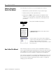
Appendix A LED Status Indicators Interpreting the Status Indicators TXD Indicator ETHERNET RXD Indicator The faceplate of the 1756-ENET/B module is provided with LED indicators that display the module status and transmit/receive status. The following table describes module health indicator displays, module status, and recommended action: OK Indicator If the OK indicator is: then module status is: take this action: Off Not operating. Apply chassis power.
A-2 LED Status Indicators Publication 1756-UM051B-EN-P - November 2000
Appendix B 1756-ENET/B Module Web Pages Web Page Diagnostics The Ethernet module’s Web pages offer extensive internal and network diagnostics. To view the Web pages, enter the module’s IP address into Netscape or Microsoft Internet Explorer. You will see the following Web page: The module’s Web pages provide the following information: • • • • Module Information TCP/IP Configuration Diagnostic Information Chassis Who These pages are shown in the following figures.
B-2 1756-ENET/B Module Web Pages Module Information The Module Information page provides specific information about your ENET/B module, such as its serial number and firmware version. TCP/IP Configuration The TCP/IP Configuration page provides the Ethernet configuration of your module, including IP Address, Gateway Address, Subnet Mask, etc.
1756-ENET/B Module Web Pages B-3 Diagnostic Information The 1756-ENET/B module provides advanced diagnostic information via this page. This information may be useful to systems administrators and other experienced information technology personnel. As an example, selecting ENET/IP Statistics under the Miscellaneous heading opens the following window.
B-4 1756-ENET/B Module Web Pages This page provides access to detailed ENET/IP diagnostics. For example, selecting CIP (ENET/IP) Statistics opens the following window. ENET/IP (CIP) STATISTICS The CIP (ENET/IP) Statistics page provides the connection and traffic information shown above.
1756-ENET/B Module Web Pages B-5 Chassis Who The Chassis Who window shows the current configuration of the chassis in which the 1756-ENET/B module resides. It identifies all of the modules in the chassis and their slot locations.
B-6 1756-ENET/B Module Web Pages Publication 1756-UM051B-EN-P - November 2000
Appendix C Configuring the RSLinx Ethernet Communication Driver What This Appendix Contains In order to communicate with your 1756-ENET/B modules over your network you must configure the RSLinx Ethernet communication driver (AB_ETH). You can configure the AB_ETH driver with the IP addresses of all the Ethernet modules on your system. You will need this driver to download the example application programs in this manual.
C-2 Configuring the RSLinx Ethernet Communication Driver Configuring the AB_ETH Driver To configure the AB-ETH Ethernet communication driver perform the following steps: 1. Start RSLinx. 2. From the Communications menu, select Configure Drivers. The following window will open. 3. Click on the arrow to the right of the Available Driver Types box. The Available Driver Types list will appear.
Configuring the RSLinx Ethernet Communication Driver C-3 4. Select Ethernet Devices and click on Add/New. You will be prompted to name the driver. 5. Select the default driver name (e.g., AB_ETH-1) or type in your own name and click on OK. The Configure driver window will appear with the Station Mapping page open. 6. Click on Add New and enter the IP address of your 1756-ENET/B module (e.g., 130.130.130.2).
C-4 Configuring the RSLinx Ethernet Communication Driver 7. Repeat step 6 for each additional Ethernet module you need to access. 8. When you are done entering the IP addresses, click on Apply. 9. Click on OK to close the Configure driver window. The new driver will appear in the list of configured drivers. (Your list will display the drivers you have configured on your workstation.) 10.
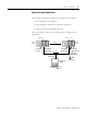
Appendix D 1756-ENET/B Support of ControlLogix Gateway Communication Using the 1756-ENET/B Module in a ControlLogix Gateway The 1756-ENET/B Ethernet module supports ControlLogix Gateway communication of control and information data between Ethernet and other networks, including ControlNet, DeviceNet, and Data Highway Plus. The following figure shows an example of a typical ControlLogix gateway system.
D-2 1756-ENET/B Support of ControlLogix Gateway Communication Publication 1756-UM051B-EN-P - November 2000
Appendix E Example Network Configurations What This Appendix Contains This appendix shows examples of Ethernet control networks, along with the RSLogix 5000 I/O configurations for those networks. You configure these networks using the procedures described in this manual, adding each remote 1756-ENET/B module and its I/O modules to the local ENET/B module in turn as you build your system.
E-2 Example Network Configurations Small System Example An example small system is shown below, consisting of a local chassis with a Logix 5550 controller and a 1756-ENET/B module serving as a network scanner, and two remote chassis with 1756-ENET/B modules serving as adaptors for the I/O modules in those chassis.
Example Network Configurations Expanded System with FLEX I/O E-3 The following figure shows the previous network with FLEX I/O added to the system. Slot 0 1 Slot 1 2 3 Local Chassis Remote Chassis #1 Logix5550 Controller 1756-ENET/B 1756-ENET/B Slot 0 1 1756-OB16I Digital Output 1756-IB16 Digital Input Remote Chassis #2 Ethernet Switch 1756-OF6VI Analog Output PC Workstation 1756-ENET/B Flex I/O The RSLogix 5000 I/O Configuration for this network is shown below.
E-4 Example Network Configurations Larger Control Networks Larger control networks may use additional local ENET/B modules communicating with remote chassis. A partial system is shown below. Control Processor I/O 1756-ENET/B 1756-ENET/B 1756-ENET/B I/O Ethernet Switch I/O 1756-ENET/B I/O 1756-ENET/B I/O 1756-ENET/B I/O 1756-ENET/B To addtional remote chassis The partial RSLogix 5000 I/O Configuration for this network is shown in the following figure. .
Appendix F Electronic Keying ATTENTION ! Specifying Electronic Keying 1 Be extremely cautious if you disable electronic keying. If used incorrectly, this option can lead to personal injury or death, property damage, or economic loss. You specify electronic keying to ensure that a module being inserted or configured is of the proper type and firmware revision.
F-2 Electronic Keying Publication 1756-UM051B-EN-P - November 2000
Index A about the 1756-ENET/B module 1-1 to 1-5 control and information protocol (CIP) 1-4 mixing rack optimized and direct connections 1-3 module features 1-1 producer/consumer model 1-4 rack optimized and direct connections 1-2 to 1-3 requested packet interval (RPI) 1-5 what the module does 1-2 about this user manual P-1 to P-8 analog I/O with direct connection 6-1 to 6-12 add I/O module to configuration 6-4 to 6-7 create the example application 6-3 to 6-11 download program 6-11 edit controller tags 6-8 t
2 Index installing the ethernet module 2-1 to 2-8 applying chassis power 2-7 checking power supply and module status 2-8 connecting to the ethernet network 2-6 determining module slot location 2-3 inserting module in the chassis 2-4 insertion and removal under power 2-2 preparing the chassis 2-2 removing or replacing the module 2-5 wiring the ethernet connector 2-6 IP address 3-3 to 3-4 L ladder program 5-14 to 5-15, 6-10 to 6-11, 7-6 to 7-7 LED status indicators A-1 M add local ENET module to I/O conf
Allen-Bradley Publication Problem Report Pub. Name ControlLogix Ethernet Communication Interface Module User Manual Cat. No. 1756-ENET/B Check Problem(s) Type: Pub. No. 1756-UM051B-EN-P Pub. Date November 2000 Part No.
( ) Other Comments PLEASE FOLD HERE BUSINESS REPLY MAIL FIRST-CLASS MAIL PERMIT NO.
Back Cover Publication 1756-UM051B-EN-P - November 2000 2 Supersedes Publication 1756-UM051A-EN-P - August 1997 PN 957400-29 © 2000 Rockwell International Corporation. Printed in the U.S.A.