Installation Instructions ControlLogix Ethernet Communication Interface Module Catalog Number 1756-ENET/B Use this manual as a guide to install the ControlLogix™ Ethernet™ Communication Interface Module. This table identifies what this manual contains and where to find specific information.
ControlLogix Ethernet Communication Interface Module Important User Information Because of the variety of uses for the products described in this publication, those responsible for the application and use of these products must satisfy themselves that all necessary steps have been taken to assure that each application and use meets all performance and safety requirements, including any applicable laws, regulations, codes and standards.
ControlLogix Ethernet Communication Interface Module 3 avoid a potential hazard, and recognize the consequences of a potential hazard: WARNING ! ATTENTION ! IMPORTANT Identifies information about practices or circumstances that can cause an explosion in a hazardous environment, which may lead to personal injury or death, property damage, or economic loss. Identifies information about practices or circumstances that can lead to personal injury or death, property damage, or economic loss.
ControlLogix Ethernet Communication Interface Module ATTENTION ! Environment and Enclosure This equipment is intended for use in a Pollution Degree 2 industrial environment, in overvoltage Category II applications (as defined in IEC publication 60664-1), at altitudes up to 2000 meters without derating. This equipment is supplied as "open type" equipment.
ControlLogix Ethernet Communication Interface Module 5 ATTENTION ! Preventing Electrostatic Discharge This equipment is sensitive to electrostatic discharge, which can cause internal damage and affect normal operation. Follow these guidelines when you handle this equipment: • Touch a grounded object to discharge potential static. • Wear an approved grounding wriststrap. • Do not touch connectors or pins on component boards. • Do not touch circuit components inside the equipment.
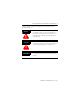
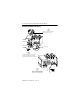
ControlLogix Ethernet Communication Interface Module Identifying Module Components Use this illustration to identify the external features of the Ethernet module.
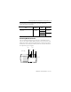
ControlLogix Ethernet Communication Interface Module 7 For information about installing these products, refer to the publications listed in this table. Chassis Type Series B: 1756-A4, -A7, -A10, -A13, -A17 Chassis Installation Power Supply Power Supply Installation Pub. No. 1756-IN080 1756-PA72/B Pub. No. 1756-5.67 1756-PB72/B 1756-PA75/A 1756-PB75/A Pub. No. 1756-5.78 Determining Module Slot Location You can install the module in any slot in the ControlLogix chassis.
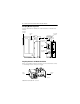
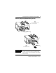
ControlLogix Ethernet Communication Interface Module Installing the Module in the Chassis 1 Align the circuit board with top and bottom guides in the chassis. Circuit Board 2 Slide the module into the chassis. Make sure the module backplane connector properly connects to the chassis backplane. 3 The module is properly installed when it is flush with the power supply or other installed modules.
ControlLogix Ethernet Communication Interface Module 9 Removing or Replacing the Module (when applicable) 1 Push on upper and lower module tabs to disengage them. 2 Slide module out of chassis. IMPORTANT If you are replacing an existing module with an identical one, and you want to resume identical system operation, you must install the new module in the same slot.
ControlLogix Ethernet Communication Interface Module Installing or Removing the Module While Power Is Applied You can install or remove the module while chassis power is applied. Please observe the following precautions. WARNING ! When you insert or remove the module while backplane power is on, or you connect or disconnect the communications connectors, an electrical arc can occur. This could cause an explosion in hazardous location installations.
ControlLogix Ethernet Communication Interface Module 11 Connecting the Module to the Ethernet Network If you connect or disconnect the Ethernet cable with power applied to this module or any device on the network, an electrical arc can occur. This could cause an explosion in hazardous location installations. Be sure that power is removed or the area is nonhazardous before proceeding.
ControlLogix Ethernet Communication Interface Module IMPORTANT Connecting the module to the network via an Ethernet switch will reduce collisions and lost packets and increase network bandwidth. See the EtherNet/IP Performance and Application Guide, publication ENET-AP001, for more information.
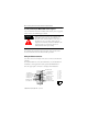
ControlLogix Ethernet Communication Interface Module 13 Checking Power Supply and Module Status Check the LED indicators to determine if the power supply and module are operating properly. ETHERNET POWER RXD TXD OK OK indicator is RED, then FLASHING RED (or is GREEN if module is configured). Power Supply indicator is GREEN If the Power Supply and OK indicators are not in the states described above refer to the following troubleshooting section.
ControlLogix Ethernet Communication Interface Module Troubleshooting the Module This table describes module health (OK) indicator displays, module status, and recommended action: If the OK indicator is then module status is take this action Off Not operating. Apply chassis power. Verify module is completely inserted into chassis and backplane. Red, then flashing red or flashing green Performing powerup diagnostics. None, normal operation. Green Operating. None. Red flashing Not configured.
ControlLogix Ethernet Communication Interface Module 15 Hazardous Location Information The following information applies when operating this equipment in hazardous locations: Informations sur l’utilisation de cet équipement en environnements dangereux : Products marked “CL I, DIV 2, GP A, B, C, D” are suitable for use in Class I Division 2 Groups A, B, C, D, Hazardous Locations and nonhazardous locations only.
ControlLogix Ethernet Communication Interface Module Specifications Module Location Any slot in the ControlLogix chassis Maximum Backplane Current Load 900mA @ 5.1V dc 350mA @ 24V dc from I/O chassis backplane Power Dissipation 13.
ControlLogix Ethernet Communication Interface Module 17 Enclosure Type Rating None (open-style) Conductors Wiring Category 802.
ControlLogix Ethernet Communication Interface Module IMPORTANT This equipment is not resistant to sunlight or other sources of UV radiation. The secondary of a current transformer shall not be open-circuited when applied in Class I, Zone 2 environments. Equipment of lesser Enclosure Type Rating must be installed in an enclosure providing at least IP54 protection when applied in Class I, Zone 2 environments. This equipment shall be used within its specified ratings defined by Allen-Bradley.
ControlLogix Ethernet Communication Interface Module 19 Publication 1756-IN053D-EN-P - June 2002
Publication 1756-IN053D-EN-P - June 2002 Supersedes Publication 1756-IN053C-EN-P - May 2001 PN 957689-13 Copyright © 2002 Rockwell Automation, Inc. All rights reserved. Printed in the U.S.A.