Installation Instructions ControlLogix EtherNet/IP Bridge Module Catalog Number 1756-ENBT Use this document as a guide to install the module. Note that this document describes hardware installation only. For configuration information, refer to the EtherNet/IP Modules User Manual, publication number ENET-UM001, available online at www.rockwellautomation.com/literature. The following table lists the contents of this document and where to find specific information.
ControlLogix EtherNet/IP Bridge Module I Important User Information Solid state equipment has operational characteristics differing from those of electromechanical equipment. Safety Guidelines for the Application, Installation and Maintenance of Solid State Controls (Publication SGI-1.1 available from your local Rockwell Automation sales office or online at http://www.ab.com/manuals/gi) describes some important differences between solid state equipment and hard-wired electromechanical devices.
ControlLogix EtherNet/IP Bridge Module 3 Environment and Enclosure ATTENTION This equipment is intended for use in a Pollution Degree 2 industrial environment, in overvoltage Category II applications (as defined in IEC publication 60664-1), at altitudes up to 2000 meters without derating. This equipment is considered Group 1, Class A industrial equipment according to IEC/CISPR Publication 11.
ControlLogix EtherNet/IP Bridge Module Removal and Insertion Under Power WARNING When you insert or remove the module while backplane power is on, an electrical arc can occur. This could cause an explosion in hazardous location installations. Be sure that power is removed or the area is nonhazardous before proceeding. Repeated electrical arcing causes excessive wear to contacts on both the module and its mating connector. Worn contacts may create electrical resistance that can affect module operation.
ControlLogix EtherNet/IP Bridge Module 5 North American Hazardous Location Approval The following information applies when operating this equipment in hazardous locations: Informations sur l’utilisation de cet équipement en environnements dangereux: Products marked “CL I, DIV 2, GP A, B, C, D” are suitable for use in Class I Division 2 Groups A, B, C, D, Hazardous Locations and nonhazardous locations only.
ControlLogix EtherNet/IP Bridge Module The following information applies when operating this equipment in hazardous locations: WARNING EXPLOSION HAZARD Informations sur l’utilisation de cet équipement en environnements dangereux: AVERTISSEMENT • Do not disconnect equipment unless power has been removed or the area is known to be nonhazardous. • Do not disconnect connections to this equipment unless power has been removed or the area is known to be nonhazardous.
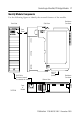
ControlLogix EtherNet/IP Bridge Module 7 Identify Module Components Use the following figure to identify the external features of the module.
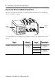
ControlLogix EtherNet/IP Bridge Module Prepare the Chassis for Module Installation Before you install the module, you must install and connect a ControlLogix chassis and power supply. 1756-A4 Chassis Power Supply 20805-M For information on installing these products, refer to the publications listed below. Chassis Type Chassis Installation Power Supply Power Supply Installation Series B: 1756-A4, -A7, -A10, -A13 Pub. No. 1756-IN080 1756-PA72/B Pub. No. 1756-5.
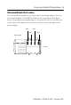
ControlLogix EtherNet/IP Bridge Module 9 Determine Module Slot Location You can install the module in any slot in the ControlLogix chassis. You can also install multiple 1756-ENBT modules in the same chassis. The figure below shows chassis slot numbering in a 4-slot chassis. Slot 0 is the first slot and is always the leftmost slot in the rack (the first slot to the right of the power supply).
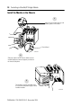
ControlLogix EtherNet/IP Bridge Module Install the Module in the Chassis 1 Align the circuit board with top and bottom guides in the chassis. Circuit Board 31275-M 2 Slide the module into the chassis. Make sure the module backplane connector properly connects to the chassis backplane. 3 The module is properly installed when it is flush with the power supply or other installed modules.
ControlLogix EtherNet/IP Bridge Module 11 Remove or Replace the Module (when applicable) 1 Push on upper and lower module tabs to disengage them. 31277-M 31278-M 2 Slide module out of chassis. IMPORTANT If you are replacing an existing module with an identical one, and you want to resume identical system operation, you must install the new module in the same slot.
ControlLogix EtherNet/IP Bridge Module Install or Remove the Module Under Power This module is designed to be installed or removed while chassis power is applied. WARNING When you insert or remove a module while backplane power is on, an electrical arc may occur.
ControlLogix EtherNet/IP Bridge Module 13 Wire the Ethernet Connector Use an RJ45 connector to connect to the EtherNet/IP network. Wire the connector according to the following illustration: 8 ------ NC 7 ------ NC 6 ------ RD5 ------ NC 4 ------ NC 3 ------ RD+ 2 ------ TD1 ------ TD+ 8 1 RJ 45 For detailed EtherNet/IP connection information, see the EtherNet/IP Media Planning and Installation Guide, publication number ENET-IN001.
ControlLogix EtherNet/IP Bridge Module Attach the RJ45 connector to the Ethernet port on the bottom of the module as shown below: OR IMPORTANT 31279-M We recommend connecting the module to the network via a 100MB Ethernet switch, which will reduce collisions and lost packets and increase network bandwidth.
ControlLogix EtherNet/IP Bridge Module 15 Apply Chassis Power 31280-M Check Power Supply and Module Status Check the LED indicators and alphanumeric display to determine if the power supply and module are operating properly. Alphanumeric Display LINK NET OK LINK Power Supply indicator is GREEN. NET OK indicator is red during self-test, then green. 31281-M The alphanumeric display should cycle through the following states: “TEST PASS - OK - REV x.x,” where “x.x” is the module’s firmware revision.
ControlLogix EtherNet/IP Bridge Module Troubleshoot the Module If the alphanumeric display and LED indicators do not sequence through the expected states refer to the following troubleshooting tables. The three bi-color (red/green) LED status indicators on the 1756-ENBT module provide diagnostic information about the module and its connections to the network.
ControlLogix EtherNet/IP Bridge Module 17 Link Status Indicator The Link Status LED provides the following information: State Status Description Off No data transmission Module is not ready to communicate. Green Ready Module is ready to communicate. Flashing Green Data transmission in progress Module is communicating over the network. OK Status Indicator The OK Status LED provides the following module information: State Status Description Off No Power Module does not have 24V DC power.
ControlLogix EtherNet/IP Bridge Module Specifications Module Location Any slot in the ControlLogix chassis Backplane Current (mA) at 5V.1V dc 700mA Backplane Current (mA) at 24V 3mA Isolation Voltage, Continuous 30V Tested to 707V dc for 60 seconds Power Dissipation, Max. 3.65W Conductors Wire Size Category 802.3 compliant - shielded or unshielded twisted pair Ethernet Connector RJ45 Cat.
ControlLogix EtherNet/IP Bridge Module 19 Shock, Non-operating IEC60068-2-27 (Test Ea, Unpackaged shock): 50g Emissions CISPR 11: Group 1, Class A ESD Immunity IEC 61000-4-2: 6kV contact discharges 8kV air discharges Radiated RF Immunity IEC 61000-4-3: 10V/m with 1kHz sine-wave 80%AM from 30MHz to 2000MHz 10V/m with 200Hz 50% Pulse 100%AM at 900Mhz 10V/m with 200Hz 50% Pulse 100%AM at 1890Mhz EFT/B Immunity IEC 61000-4-4: ±2kV at 5kHz on communications ports Surge Transient Immunity IEC 61000-4-5
Certifications2 (when product is marked) UL UL Listed Industrial Control Equipment CSA CSA Certified Process Control Equipment CSA CSA Certified Process Control Equipment for Class I, Division 2 Group A,B,C,D Hazardous Locations FM FM Approved Equipment for use in Class I Division 2 Group A,B,C,D Hazardous Locations CE European Union 89/336/EEC EMC Directive, compliant with: EN 50082-2; Industrial Immunity EN 61326; Meas./Control/Lab.